background image

6. Installation preparations 

│ gb 


13 

6.3 Duct 

1.  Debur edges on the inside of the duct. 

NOTICE 

Risk of damage to flexible 
ducts (folded spiral-seams 
ducts) caused by spring hooks. 

Snap off the spring hooks prior 
to installation of the flexible ducts. 


2.  If necessary snap off the two spring  

hooks [1]. 

3.  Perform installation preparations as 

described in Chapter 6.1. 


6.4 Fan 

1.  Unpack fan unit. 

2.  Remove internal grille/shutter frame [8]. 

For loosening unlock both safety catches 
(

 Fig. D) with a screwdriver. 


7. Installation 


7.1 Installing housing 

1.  Insert housing [4] in wall breakthrough/wall 

sleeve/duct. 

2.  Align housing [4] horizontally, mark the 

two dowel holes, drill the dowel holes Ø 6 
mm and insert the dowels. 


NOTICE 

Danger of short circuits and 
damage to unit. If the power 
cable is incorrectly fed or if 
the cable grommet is not fitted 
correctly, water may penetrate 
into the fan housing and the 
degree of protection cannot 
be guaranteed. 

Pierce the cable grommet  [2] or 
[3] such that the cable grommet 
tightly clasps the power cable 
(cut in a round shape, no slot). 

Guide the surface- or recessed-
mounted cables correctly into 
the intended cable grommet. 

3.  Carefully press out the cable grommet [2] 

or [3] from the housing [4], then remove 
and pierce a round hole in the cable 
grommet by means of a grommet puncher. 
Use cable grommet [3] for surface 
installation and cable grommet [2] for 
recess installation. 

4.  Reinsert the removed cable grommet in  

a professional manner, provide sealing  
on site if necessary. 

5.  Guide the power cable into the connection 

area such that the cable grommet fits 
around the cable sheathing completely. 


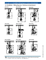
7.2 Electrical connection 


DANGER 

Danger to life from electric 
shock. 

Prior to access to the connection 
terminals switch off all supply 
circuits. Switch off main fuses, 
secure against being accidentally 
switched back on and position a 
visible warning sign. 


NOTICE 

Risk of damage to unit in the 
event of short-circuits. 

Cut off and insulate PE conductor 
and individual cable cores that 
are not required! 


NOTICE 

The opening function of the 
shutter frame (K fans) will be 
hindered by protruding cables! 

Cut off and insulate PE conductor 
and individual cable cores that 
are not required! 


NOTICE 

Risk of damage to the unit if 
ESD sensitive components on 
the board are touched [5.2] / 
[5.3].  

Avoid direct touching of the 
components or contact surfaces. 


1.  Switch the mains fuse off. 

2.  Only lay single cable cores in the unit. 

Remove the power cable cladding and 
insulate the ends of the cable cores. 

Summary of Contents for ECA 120 SERIES

Page 1: ...tilator Small Room Fan A rateur pour petits locaux ECA 120 ECA 120 K Montage und Betriebsanleitung Mounting and Operating instructions Instructions de montage et Mode d emploi www m aico ventilatoren...

Page 2: ...zum Produkt Im Internet unter maico ventilatoren com Mounting an Operating instructions Page 9 Wiring diagrams Page 24 Scope of delivery Small room fan ECA 120 or ECA 120 K Mounting and operating ins...

Page 3: ...A B C D...

Page 4: ...den Anweisungen Bewahren Sie diese Anleitung f r einen sp teren Gebrauch gut auf 1 1 Installationspersonal Die Montage ist nur durch Fachkr fte zul ssig Der elektrische Anschluss darf nur von Elektro...

Page 5: ...hzahlsteuerbar F Ger te k nnen unabh ngig von der Beleuchtung per optionalem Lichtschalter bedient werden Bei Licht an startet die Automatik Wird das Licht ausgeschaltet l uft das Ger t weiter bis die...

Page 6: ...en Die maximal zul ssige Druckdifferenz pro Wohneinheit betr gt 4 Pa VZ F KVZ und KF Ger te St rfestigkeit nach EN 55014 2 je nach Impulsform und Energieanteil 1000 bis 4000 V Bei Betrieb mit Leuchtst...

Page 7: ...resultierenden Gefahren verstehen Kinder d rfen nicht mit dem Ger t spielen Reinigung und Benutzer Wartung d rfen nicht von Kindern ohne Beaufsichtigung durchgef hrt werden 6 Montagevorbereitungen 6 1...

Page 8: ...n Leitungst lle ordnungsgem einf hren 3 Leitungst lle 2 oder 3 vorsichtig aus dem Geh use 4 dr cken herausnehmen und mit einem T llenstecher kreisrund durchsto en F r Aufputzinstallation Leitungst lle...

Page 9: ...u den Anschluss klemmen alle Versorgungsstrom kreise abschalten Netzsicherung ausschalten gegen Wieder einschalten sichern und ein Warnschild sichtbar anbringen ACHTUNG Ger tebesch digung bei falschem...

Page 10: ...typen F KF 0101 1255 0000 10 ECA 120 K Thermo Bimetall E180 0913 9100 12 ECA 120 Innengitter ECA 120 K Klappenrahmen 0059 1010 9000 0059 1011 9001 Bei R ckfragen Maico Elektroapparate Fabrik GmbH Stei...

Page 11: ...instructions safe for use later on 1 1 Installation staff Installation is only permitted when carried out by trained specialists Only qualified electricians are permitted to make the electrical conne...

Page 12: ...it not speed controllable F units can be operated indepen dently of the lighting using the optional light switch The automatic operating mode commences when Light on If the light is switched off the u...

Page 13: ...entilated fireplaces The maximum permitted pressure difference per living unit is 4 Pa VZ F KVZ and KF units Resistance to interference according to EN 55014 2 depending on pulse shape and energy comp...

Page 14: ...y have been instructed about the safe operation of the unit and can understand the resulting risks thereof Children must not play with the unit Cleaning and maintenance must not be carried out by chil...

Page 15: ...efully press out the cable grommet 2 or 3 from the housing 4 then remove and pierce a round hole in the cable grommet by means of a grommet puncher Use cable grommet 3 for surface installation and cab...

Page 16: ...hock Prior to access to the connection terminals switch off all supply circuits Switch off main fuses secure against being accidentally switched back on and position a visible warning sign NOTICE Risk...

Page 17: ...strip E180 0913 9100 12 ECA 120 internal grille ECA 120 K Shutter frame 0059 1010 9000 0059 1011 9001 In the case of questions Maico Elektroapparate Fabrik GmbH Steinbeisstra e 20 78056 Villingen Schw...

Page 18: ...ilisation du ventilateur Respectez les instruc tions Conservez ces instructions pour une utilisation ult rieure 1 1 Installateurs Le montage est exclusivement r serv des professionnels Le branchement...

Page 19: ...e et d sactive automatiquement le ventilateur Luminosit de mise en marche sur l appareil au minimum 30 lx luminosit d arr t sur l appareil au maximum 0 3 lx Appareil vitesse non variable Les appareils...

Page 20: ...de l air l int rieur du logement doit tre r alis e de telle mani re que l air en provenance de la cuisine de la salle de bains et des toilettes ne puisse pas se propager dans les pi ces d habitation...

Page 21: ...l appareil sont rigoureusement interdites et d gagent le fabricant de toute responsabilit et garantie 5 2 Comportement s r et correct lors du fonction nement Risque de blessure en pr sence d objets d...

Page 22: ...ine 1 barber les bords de l int rieur de la gaine ATTENTION Risque d endommagement des gaines souples tuyaux agraf s par les crochets ressort Avant le montage dans les gaines souples rompre les mousqu...

Page 23: ...et les fils non utilis s ATTENTION Risque d endommagement de l appareil par contact avec des composants menac s DES sur platine 5 2 5 3 viter un contact direct des composants ou des surfaces de contac...

Page 24: ...ctionnement consulter un lectricien qualifi Les r parations sont exclusivement r serv es des lectriciens qualifi s DANGER Danger de mort par lectrocution Avant d acc der aux bornes couper tous les cir...

Page 25: ...icien sp cialis Chapitre 1 peut se charger du d montage DANGER Danger de mort par lectrocution Avant d acc der aux bornes couper tous les circuits d alimentation lectrique D sactiver le fusible secteu...

Page 26: ...VZ ECA 120 P ECA 120 24 V ECA 120 KVZ ECA 120 KF ECA 120 F ECA 120 K ECA 120 KP Maico Elektroapparate Fabrik GmbH Steinbeisstr 20 78056 Villingen Schwenningen Germany Service 49 7720 694 447 technik...

Reviews: