Maico BSB FSD-C Series Installation, Operation And Maintenance Instructions Download Page 8

8

 Actuator Orientation Change / Replacement 

8

.1 

8

.2 

8

.3 

8

.4 

8

.5 

8

.6 

8

.7 

If required, the orientation may be changed to +90° or -90° from default ‘in-

line-with-duct’. 

Ensure power to actuator is removed and allow actuator to travel to end 

position. 

Unscrew the 8mm AF head screw (central motor retaining screw) and 

remove the set-point assembly

.


Remove the 10mm AF head screws (motor body retaining bolts). (It may be 

necessary to partially wind the actuator a few degrees with the aid of the 

manual reset key to release residual torque). 

Remove the actuator and refit in new position w

wiitthhoouutt changing the blade’s 

position. 
Secure with the 10mm AF head screws (5Nm), followed by the ’

set point


assembly’ and 8mm AF head screw (3Nm). 

Test (refer to section 1

2

). 

9

 Setting of Damper mid set-point Position (optional) 

9

.1 

9

.2 

9

.3 

Dampers are supplied with actuators set to travel to ‘fully open’ position by 

default.  

Optionally, dampers can be set so that the ‘open position’ is restricted to 

between 30° to 90° (60° range). This is for system air balancing purposes, 

should it be required. 

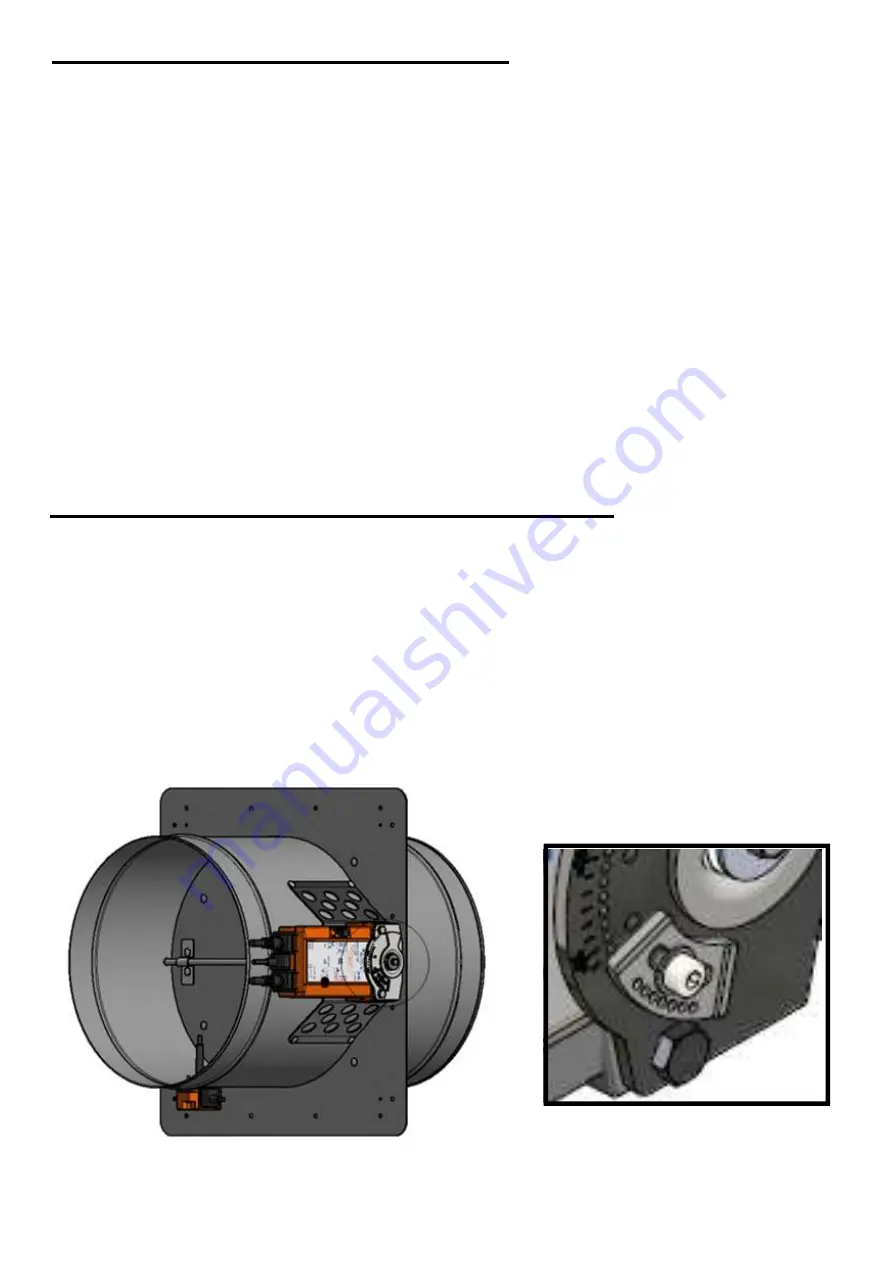
To utilise set-point positioning, temporarily release actuator

 (using 2.5mm AF 

allen key),

 unscrew  and reposition the positional limiter engaging into the 

2mm dia holes (as below).

Note: Wiring (section 9

.5

), If using "open damper status" indication

.


8.

5

8.

6

Retighten the retaining screw to approx. 3Nm.

Re

-

apply power and check 

desired

open position is attained.

9  Wiring

9.1
9.2
9.3

Refer to electrical specification on back page of this document

.

Dampers are supplied with actuators factory fitted and tested.
Connect wires in accordance with the wiring details  below.
Test

.

 (Refer to section 10

)

9

.

4


9.

4

Make the following connections to achieve damper status indication:

Closed - use 1&2

open when not fully open - use 4&6

open indication when mid set point function - use 1&3

4

7

Summary of Contents for BSB FSD-C Series

Page 1: ...E READ IN THEIR ENTIRETY BEFORE COMMENCING WORK TO ENSURE COMPLIANCE BEFORE COMMENCING WORK TO ENSURE COMPLIANCE Dampers will only be CE marked if Installed as tested These instructions are followed A...

Page 2: ...il required Dampers are designed for installation within internal normal dry filtered H V systems 1 FSD C Damper Installation Operating Maintenance Instructions 1 Health and Safety 1 1 Only competent...

Page 3: ...SD C M9 6 1 Preferably prepare opening whilst building wall or cut opening if wall already exists 3 Equipment required 3 1 Equipment and tools will vary dependent upon the fire barrier construction th...

Page 4: ...trally in wall opening width height Using drywall screws fix Installation Plate to wall using drywall screws Important Ensure the screws pick up the track lining the aperture so that the proper fire i...

Page 5: ...pping blunt point screws quantity to suit damper size These are optional accessories at the time of purchase of dampers 7 2 Prepare and install damper into position 7 2 1 Remove the clamp plate from t...

Page 6: ...damper cleats and join to upper drop rods with a coupling nut and lock nuts as per view C of the installation drawing 7 2 13 Fit a pair of M10 nuts to each lower drop rod underneath the damper bottom...

Page 7: ...al and ST4 8x19 safety self tapping screws 7 3 9 Tighten all screws to securely sandwich the FFC material 7 3 10 If necessary for aesthetic purposes only trim any excess FFC material protruding near t...

Page 8: ...n new position w wi it th ho ou ut t changing the blade s position Secure with the 10mm AF head screws 5Nm followed by the set point assembly and 8mm AF head screw 3Nm Test refer to section 12 9 Setti...

Page 9: ...Closed use 1 2 open when not fully open use 4 6 open indication when mid set point function use 1 3 8 5 8 6 Retighten the retaining screw to approx 3Nm Re apply power and check desired open position...

Page 10: ...11 Actuator and Thermal Fuse Access Maintenance Install zone 5 Default Position 2 9...

Page 11: ...zones in the below images d and blue zones in the below images 10...

Page 12: ...can lead to a build up of dust dirt on damper surfaces 12 13 The PML actuator is maintenance free 6 10 Commissioning Maintenance and Test 10 1 Pre check BEFORE power is established Check the actuator...

Page 13: ...a couple of times then remove any excess lubricant Casing dented damaged or not round Minor damage may be corrected carefully with a mallet BSB always recommend replacement of damaged dampers Foreign...

Page 14: ...Electrical details 24V Grey actuator case 230V Orange actuator case 13...

Page 15: ...Print name Signature Company Date Actuator mid point setting circle if applicable 30 35 40 45 50 55 60 65 70 75 80 85 90 FAIL SAFE POSITION POWER OFF position Tick appropriate FINAL INSPECTION BY Prin...

Page 16: ...sult from continuous product development The information contained within this brochure is correct at the time of going to press For full details of the complete BSB Product Range please refer to our...

Reviews: