26
Magtrol Model 6530 Three-Phase Power Analyzer
Chapter 3 – Installation/Configuration
SETUP
3.3.4
A
MP
S
CALING
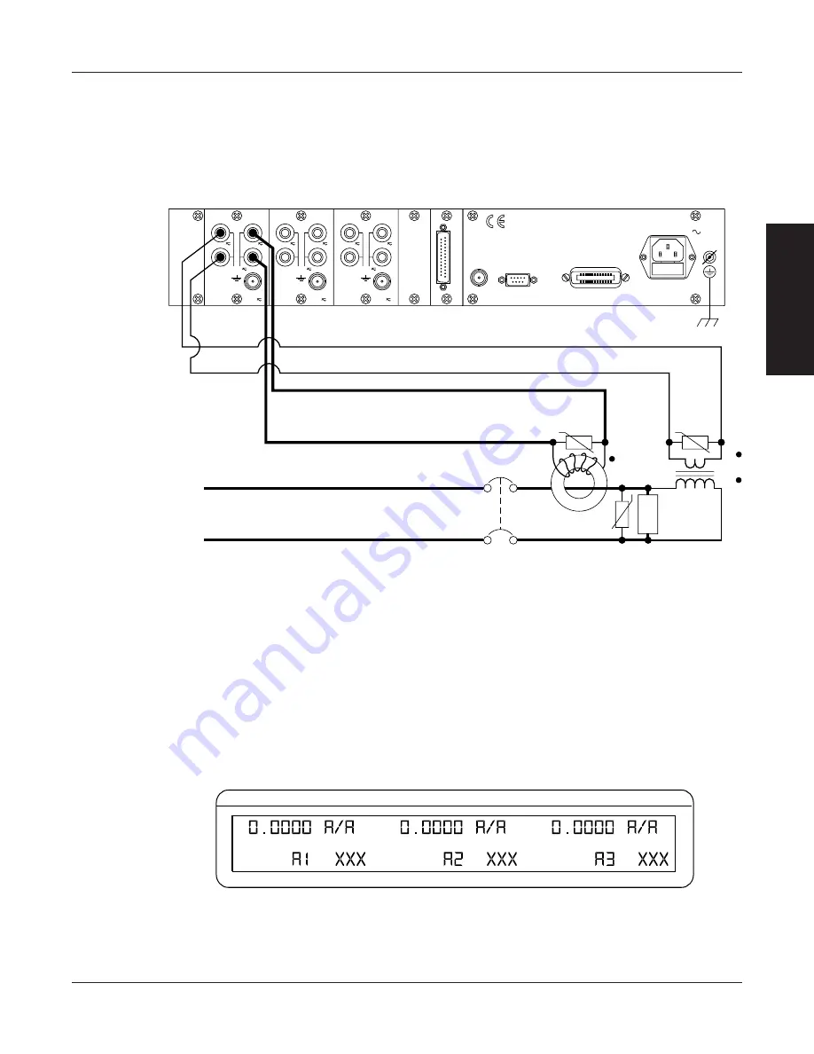
The current measurement range can be extended by using a current transformer. Frequency response
will be determined by the characteristics of the transformer used.
3.3.4.1
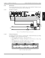
Hardware Connection
EARTH
LINE
HIGH
LOW
MOV 2
MOV 3
PT
CT
LOAD
CB
MOV 1
A
N
A
L
O
G
O
U
T
P
U
T
A
±
±
V
±
V
±
V
±±
±
±
A
V
A
±
EXT.
SYNC.
EARTH
GROUND
20VA 50/60Hz
FUSE (5x20mm)
CAUTION: DOUBLE POLE FUSING
120V UL/CSA 250mA 250V SB
240V IEC 160mA 250V T
RS-232C
GPIB/IEEE-488
MAGTROL INC.
20 A
AMPS
750 V
VOLTS
MAX.
EXT.
MAX.
1000 V
MAX.
MAX.
±10 V
SENSOR
20 A
AMPS
750 V
VOLTS
MAX.
EXT.
MAX.
1000 V
MAX.
MAX.
±10 V
SENSOR
20 A
AMPS
750 V
VOLTS
MAX.
EXT.
MAX.
1000 V
MAX.
MAX.
±10 V
SENSOR
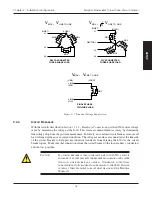
Figure 3–21 Current/Potential Transformer Connection
3.3.4.2
Software Configuration
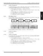
To configure the 6530 amp scaling for a current transformer, complete the following steps utilizing
the USER MENU located on the front panel of the unit.
1. Turn on the 6530. See
Section 3.1 – Powering Up the 6530
.
2. Press ENTER button. The display should appear as shown in
Figure 2–3 Device Setup
Menu
.
3. Press
and
buttons until AMP SCALING appears in the display.
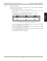
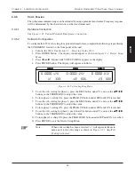
4. Press ENTER button. The display will appear as follows.
CURRENT
VOLTAGE
POWER/PF
Figure 3–22 Amp Scaling Setup Menu


