23
Magtrol Model 6530 Three-Phase Power Analyzer
Chapter 3 – Installation/Configuration
SETUP
3.3.1.2
Software Configuration
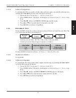
To configure the 6530 to coincide with the wiring on the rear panel, complete the following steps
utilizing the USER MENU located on the front panel of the unit.
1. Turn on the 6530. See
Section 3.1 – Powering Up the 6530
.
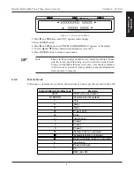
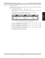
2. Press ENTER button. The display should appear as shown in
Figure 2–3 Device Setup
Menu
.
3. Press
and
buttons until WIRING MODE appears in the display.
4. Press
and
buttons until desired wiring mode is reached.
5. Press ENTER to exit Device Setup Menu.
3.3.2
M
EASUREMENT
F
ILTER
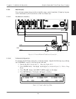
During the RMS calculations, in the signal-processing path, there is a digital low-pass filter. The
user can program the filter’s cutoff frequency.
Measured
Value
(Value)²
Filter
Square
Root
•
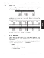
Selections include 1 Hz, 2 Hz, 5 Hz, 10 Hz, 20 Hz, 50 Hz and 100 Hz .
•
Correlation between filter setting and response is as follows:
g
n
i
t
t
e
S
r
e
t
l
i
F
e
g
n
a
h
C
l
a
n
g
i
S
o
t
e
s
n
o
p
s
e
R
e
m
o
c
t
u
O
w
o
L
w
o
l
S
g
n
i
d
a
e
R
e
l
b
a
t
S
h
g
i
H
t
s
a
F
g
n
i
d
a
e
R
e
l
b
a
t
s
n
U
For more detailed information on theory, see
Chapter 4 – Operating Principles
.
3.3.2.1
Hardware Connection
Not applicable.
3.3.2.2
Software Configuration
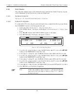
To configure the 6530 measurement filter, complete the following steps utilizing the USER MENU
located on the front panel of the unit.
1. Turn on the 6530. See
Section 3.1 – Powering Up the 6530
.
2. Press ENTER button. The display should appear as shown in
Figure 2–3 Device Setup
Menu
.
3. Press
and
buttons until MEASUREMENT FILTER appears in the display.
4. Press
and
buttons until desired measurement filter is reached.
5. Press ENTER to exit Device Setup Menu.

