26
Magtrol Model 5100 Single Phase Power Analyzer
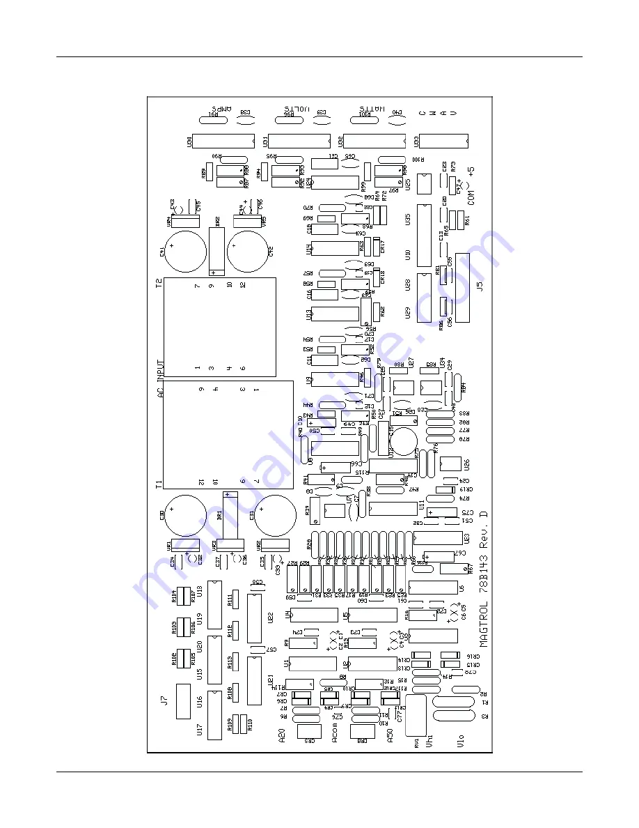
Appendix A: Schematics
PARTS LOCATION FOR CIRCUIT BOARD 78B143
Page 1: ...uy your excess underutilized and idle equipment along with credit for buybacks and trade ins Custom engineering so your equipment works exactly as you specify Critical and expedited services Leasing R...
Page 2: ...odel 5100 Model 5100 Single Phase Single Phase Single Phase Single Phase Single Phase P P P P Power Analyzer ower Analyzer ower Analyzer ower Analyzer ower Analyzer User User User User User s Manual s...
Page 3: ...the General Electric Corporation FLUKE is a registered trademark of the John Fluke Mfg Company Microsoft is a registered trademark of the Microsoft Corporation Supercon is a registered trademark of t...
Page 4: ...rload 2 2 SPECIFICATIONS 3 Voltage 3 Current 3 Meter Impedance 3 Resolution 3 Isolation 3 Display Auto Zero 3 Analog Outputs 3 Data Acquisition 3 ANALOG 3 DIGITAL 3 Measurement Accuracy 4 Accuracy Cer...
Page 5: ...Display 9 Voltage Display 9 Watts or Power Factor 9 Mode Hold 9 Mode Avg 10 Analog Output Option 10 Figure 9 Analog Output Connections 10 5 GPIB COMMUNICATION 11 GPIB IEEE 488 11 Hardware Installation...
Page 6: ...T BALANCE 19 WATTS SCALE FACTOR 19 APPENDIX A SCHEMATICS 20 Circuit Board 78B128 LED display 20 Circuit Board 78B141 21 Circuit Board 78B142 22 Circuit Board 78B175 22 Circuit Board 78B143 23 Circuit...
Page 7: ...vi T T T T Table of R able of R able of R able of R able of Revisions evisions evisions evisions evisions Date Change Page Number s 02 07 00 Added External Shunt Connection Drawing 5...
Page 8: ...to the rear access power entry and filter module of the 5100 PA The line cord must be detached from the PA during servicing NOTE The standard 5100 is factory wired for 120 Vrms power Wiring for 240 Vr...
Page 9: ...ted The MODE indicators do not light during this power on sequencing Your 5100 PA has passed the initial check TRANSIENT OVERLOADS Connect an appropriate transient suppressor in parallel with all indu...
Page 10: ...ay indication is less than 0 5 of range the displayed value is set to ZERO Refer to SECTION 5 SPECIAL FUNCTIONS to disable the AUTO ZERO function ANALOG OUTPUTS This is an optional feature Analog AMPS...
Page 11: ...a e r f o 0 1 z H k 0 2 o t z H k 0 1 g n i d a e r f o 0 2 e g n a R p m A 0 5 z H k 1 o t z H 0 1 e g n a r p m A 0 2 s a e m a s z H k 2 o t z H k 1 e g n a r f o 0 2 C D R E W O P e g n a r A V f...
Page 12: ...aristors MOV or other PROTECTION equivalent transient suppressors connected between lines at the load across the load These suppressors are an absolute necessity when inductive loads are used In three...
Page 13: ...at the load This increases measurement accuracy by eliminating line voltage drop from the power measurement For safety an overload circuit breaker CB removes all load voltage during an over current c...
Page 14: ...EARTH 1 2 3 NEUTRAL GND INPUT AMPS 5100 PA EARTH OUTPUT LOW VOLTS HIGH GND INPUT AMPS 5100 PA EARTH OUTPUT LOW VOLTS HIGH GND INPUT AMPS 5100 PA OUTPUT LOW VOLTS HIGH MOV MOV MOV LOAD LOAD LOAD W1 W2...
Page 15: ...of these resistors should be high enough to avoid loading the lines and affecting the power measurement The general discussion from Figure 2 applies The three load impedances are equal for a balanced...
Page 16: ...ange function is always silently monitoring the current and is ready to up range the instrument if the current increases above the range full scale If the current falls below the value of the original...
Page 17: ...n permits truly integrated power measurements where power is applied intermittently or where a combination of devices require integrated measurements with interruptions between measurements NOTE WATTH...
Page 18: ...be changed by changing the DIP switch settings that are located on the rear panel and above the GPIB connector Change this address only if there is an addressing conflict with other instrumentation o...
Page 19: ...R 13 CHR 10 CALL IBFIND gpib0 gpib0 CALL IBFIND dev12 dev12 CALL IBSIC gpib0 start CLS LOCATE 23 1 PRINT Press any key LOCATE 1 1 INPUT Enter the function character s f f UCASE f wrt f eos CALL IBWRT...
Page 20: ...ral counts around zero 2 To remove the factory set calibration factors Turn the 5100 power off depress and simultaneously hold the MODE PF and the 2 AMPS range buttons as POWER is switched ON Uncalibr...
Page 21: ...S1 01 S2 R 2 5 10 20A 50A AMP AMP 5100 COM LOW HIGH VOLTS WHT LINE LOW WHT U1 U2 U7 VI LINE HIGH BLK VE U3 COM AMPS OUTPUT COM 5100 BURDEN VOLTS 3M OHM CURRENT 2 5 10 20 AMP 0 011 OHM 50 AMP 0 001 OHM...
Page 22: ...mission The MPU acquisition and conversion rate is 100 milliseconds 10 readings per second and the display updates at 500 milliseconds 2 updates per second The MPU scans all front panel pushbutton con...
Page 23: ...dental circuit inductances can be compensated for by adjusting the phase of the current wave form to be exactly in phase zero phase shift with the voltage wave form Sources of incidental circuit induc...
Page 24: ...r 15 volts DC and repeat the above step 6 Record the VOLTS readings 7 Repeat the above 6 steps for the 30 150 300 and 600 volts ranges Lethal Voltages are Used 8 Compare the above readings to the 5100...
Page 25: ...zero phase between the volts and amps at the input to the 5100 PA Refer to the calibrator instruction manuals for this adjustment procedure 1 The phase shift control should be carefully set to provide...
Page 26: ...50 VOLTS range 2 Set the voltage calibrator for 150 volts DC output 3 Note the VOLTS display reading 4 Reverse the calibrator polarity to 150 volts DC If the plus to minus display readings differ by m...
Page 27: ...a b g f c dp e d a b g f c dp e d a b g f c dp e d a b g f c dp e d a b g f c dp e d a b g f c dp e d a b g f c dp e d a b g f c dp e d a b g f c dp e d a b g f c dp e d a b g f c dp e d 1 C1 d7 d8 Co...
Page 28: ...19 1 1G 13 15 A6 A7 12 Y3 Y4 14 9 74C244 Y1 Y2 18 16 6 8 11 A4 A3 A1 2 A2 4 Y7 A8 Y8 2G 3 A5 Y6 Y5 7 5 17 19 1 1G 13 15 A6 A7 10 1 1 0 x x x RANGE SWITCH 5 0 1 0 x x x a b c d e f 2 1 0 0 x x x x don...
Page 29: ...Analyzer Appendix A Schematics CIRCUIT BOARD 78B142 HOLD PF SW2 SW1 CR1 SW3 AVG J4 CR2 CIRCUIT BOARD 78B175 BR1 PD05 T1 14A 20 10 9 4 6 7 12 10 1 3 C4 1uF C3 1uF C1 4700uF C2 1uF O I 5V 7805 Line 120...
Page 30: ...37 A50 Bal C6 9 6 C4 9 6 C12 15 C11 C8 3 15 4 15 1 2 Arms Bal R38 C7 8 Abal R59 15 R58 C18 R61 C13 Wvf 15 R53 Wcal R50 15 15 Wvf C16 15 R46 U10 R52 R117 R3 Aa Ab R103 R110 R109 R108 R106 Vb R104 Ac Va...
Page 31: ...0 1 1 0 SW d c b a 0 1 1 1 0 20A 50A 1 0 0 2A 10A 5A 0 0 0 0 0 0 0 1 0 1 1 1 0 0 1 1 150V 300V 1 600V 0 1 0 0 1 0 0 15V 30V 1 1 1 0 3Q 4Q 16 17 15 19 1Q 18 2Q 5 3D 4 4D 6 3 1D 2 2D 7Q 7D 8Q OC 12 5D 6...
Page 32: ...3 4 5 6 7 8 9 10 11 12 13 14 15 WATTS 100 WATTS 10 WATTS 1 WATTS 10000 WATTS 1000 0 0 1 0 0 0 0 0 0 0 0 4000 1 C007 R7 1 6000 0 0 0 0 0 0 0 0 0 0 0 0 0 0 0 0 0 0 0 0 0 0 0 0 0 1 C003 R3 0 1 C002 R2 0...
Page 33: ...26 Magtrol Model 5100 Single Phase Power Analyzer Appendix A Schematics PARTS LOCATION FOR CIRCUIT BOARD 78B143...
Page 34: ...d the product transportation prepaid and a description of the malfunction to the factory The instrument shall be repaired at the factory and returned to purchaser transportation prepaid MAGTROL ASSUME...
Page 35: ...uipment Have surplus equipment taking up shelf space We ll give it a new home Learn more Visit us at artisantg com for more info on price quotes drivers technical specifications manuals and documentat...