background image

6 - Operation 

DynaFlex and DynaFlex Pro| Three-way Secure Card Reader Authenticators | Installation and Operation Manual 


Page 50 of 56 (

D998200382-10

6.10


How to Enter Card Information Manually 

The device does not support on-screen entry of cardholder information.  If the solution design requires 
manual entry, that feature would need to be implemented in the host software. 

6.11


How to Select the Card Type 

Reserved. 

6.12


How to Verify the Transaction Amount 

Reserved. 

6.13


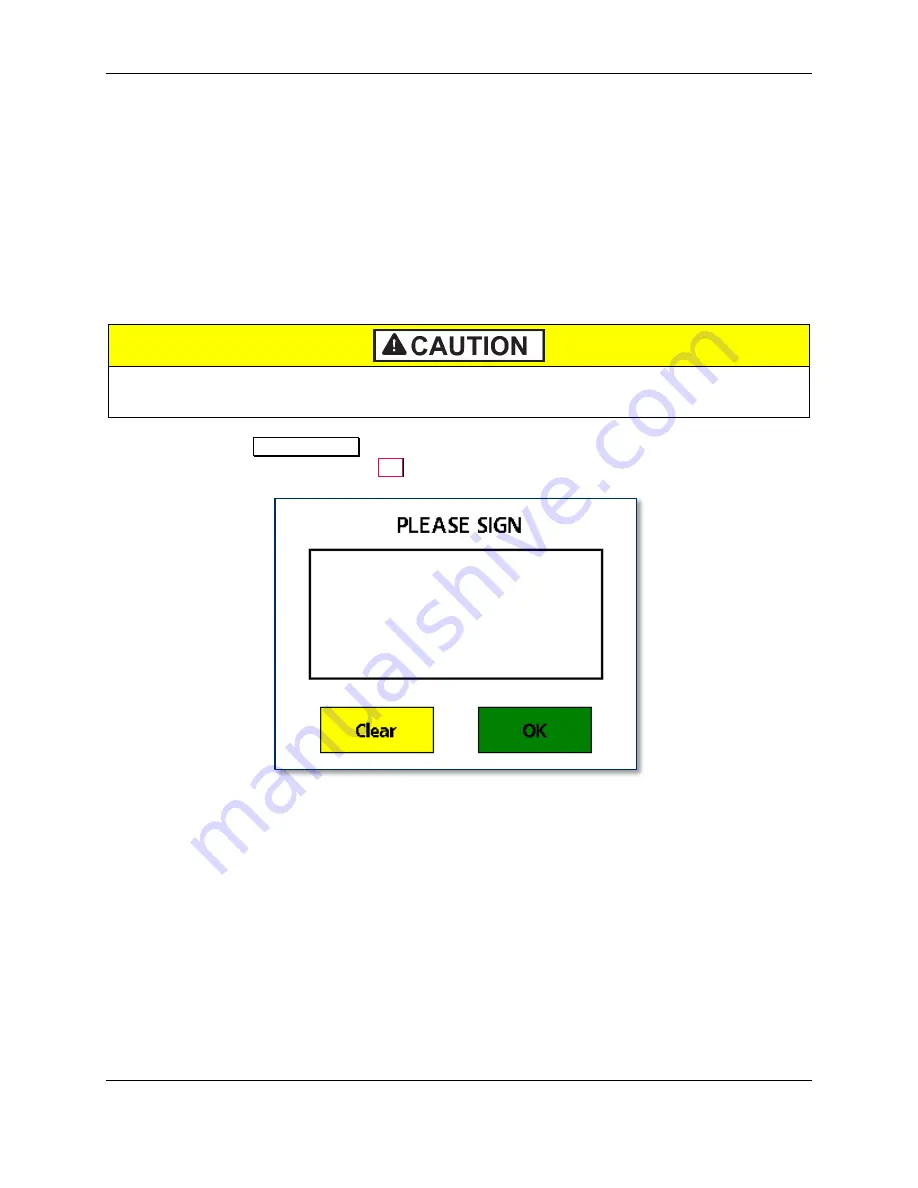
How to Use Signature Capture 


Do not use a stylus or other hard object on the touchscreen.  The touchscreen is designed 
for fingers only and can be scratched if misused. 

 
When prompted with 

PLEASE SIGN

, cardholders should use the tips of their fingers to press and glide 

against the screen to sign, then press the 

OK

 button. 


Summary of Contents for DynaProx

Page 1: ...740 I Phone 562 546 6400 I Technical Support 888 624 8350 www magtek com DynaFlex and DynaFlex Pro Three way Secure Card Reader Authenticators Installation and Operation Manual October 2020 Document Number D998200382 10 REGISTERED TO ISO 9001 2015 ...

Page 2: ...corporated Visa and Visa payWave are registered trademarks of Visa International Service Association ANSI the ANSI logo and numerous other identifiers containing ANSI are registered trademarks service marks and accreditation marks of the American National Standards Institute ANSI ISO is a registered trademark of the International Organization for Standardization UL and the UL logo are trademarks o...

Page 3: ...DynaFlex and DynaFlex Pro Three way Secure Card Reader Authenticators Installation and Operation Manual Page 3 of 56 D998200382 10 Table 0 1 Revisions Rev Number Date Notes 10 Oct 9 2020 Initial release ...

Page 4: ... disclaims any liability or warranty for goods resold in other than MagTek s original packages and for goods modified altered or treated without authorization by MagTek Service may be obtained by delivering the product during the warranty period to MagTek 1710 Apollo Court Seal Beach CA 90740 If this product is delivered by mail or by an equivalent shipping carrier the customer agrees to insure th...

Page 5: ...ED OR IMPLIED EXCEPT AS MAY BE STATED IN THIS AGREEMENT AND MAGTEK DISCLAIMS ANY IMPLIED WARRANTY INCLUDING WITHOUT LIMITATION ANY IMPLIED WARRANTY OF MERCHANTABILITY OR FITNESS FOR A PARTICULAR PURPOSE MAGTEK SHALL NOT BE LIABLE FOR CONTINGENT INCIDENTAL OR CONSEQUENTIAL DAMAGES TO PERSONS OR PROPERTY MAGTEK FURTHER LIMITS ITS LIABILITY OF ANY KIND WITH RESPECT TO THE PRODUCT INCLUDING NEGLIGENCE...

Page 6: ... for help Caution Changes or modifications not expressly approved by MagTek could void the user s authority to operate this equipment CANADIAN DECLARATION OF CONFORMITY This digital apparatus does not exceed the Class B limits for radio noise from digital apparatus set out in the Radio Interference Regulations of the Canadian Department of Communications Le présent appareil numérique n émet pas de...

Page 7: ...r UL CSA This product is recognized per UL 60950 1 2nd Edition 2011 12 19 Information Technology Equipment Safety Part 1 General Requirements CSA C22 2 No 60950 1 07 2nd Edition 2011 12 Information Technology Equipment Safety Part 1 General Requirements ROHS STATEMENT When ordered as RoHS compliant this product meets the Electrical and Electronic Equipment EEE Reduction of Hazardous Substances RoH...

Page 8: ...4 MagneSafe Security Architecture 12 1 5 Magensa Services 12 1 6 About Terminology 13 1 7 Major Components 14 2 Planning and Preparation 15 2 1 Logistical Planning 15 2 2 Network Planning 17 3 Handling and Storage 18 3 1 Handling to Avoid Damage 18 3 2 Handling to Avoid Accidental Tamper 18 4 Installation 19 4 1 About Inspection 19 4 2 About Host Software 19 4 3 Connecting to a Host 20 4 3 1 About...

Page 9: ...orce Reset 38 6 6 6 How to Turn Bluetooth LE Advertising On and Off 38 6 6 7 About Battery Warnings and Automatic Reset 39 6 6 8 About USB Suspend 40 6 6 9 About Maintenance Reset 41 6 7 How to Start a Handheld Transaction Using 802 11 Wireless 42 6 8 How to Start a Handheld Transaction Using the Bluetooth LE Connection 42 6 9 Card Reading 43 6 9 1 About Reading Cards 43 6 9 2 How to Swipe Magneti...

Page 10: ... smallest form factor at a great price DynaFlex products offer options with microsuction feet and configurable brackets assuring the cardholder a stable swipe dip or tap experience The three reading locations are all visible to the cardholder on the face of the device This intuitive positioning of the slots also ensures that bugs skimmers or shimmers can not be placed inside the device DynaFlex pr...

Page 11: ...RO PCI TOUCHSCREEN DISPLAY BLACK 802 11 WIRELESS Touchscreen USB C 802 11 Wireless 21078012 DYNAFLEX PRO PCI TOUCHSCREEN DISPLAY BLACK ETHERNET Touchscreen USB C Ethernet All models are black by default and have countertop handheld and custom mounting options Table 1 2 DynaFlex Accessories Part Description Accessory Notes 1000006016 CABLE USB A C 6FT DYNAFLEX Included with DynaFlex products 100000...

Page 12: ... display can present your logo or custom messaging is available in several different colors and depicts on screen instructions for dip tap or swipe operations They are designed for easy integration into holsters or cases for a custom solution DynaFlex products are made from molded rubberized black plastic with matching black lens on the face Custom colors and silkscreened logos are available with ...

Page 13: ...pment which can send commands and data to and receive data from the device Host types include PC and Mac computers laptops tablets and smartphones Generally the host must have software installed that communicates with the device and is capable of processing transactions During a transaction the host and its software interact with the operator such as a customer service representative while the dev...

Page 14: ...Pro except the touchscreen and its bezel are replaced with a faceplate showing the contactless indicator logo placed at the optimal contactless landing zone Figure 1 1 DynaFlex Pro Major Components Figure 1 2 shows the major components of the optional charging cradle The drain holes provide drainage of liquid spills from the top surface of the cradle out through the bottom The nesting feature allo...

Page 15: ...itional support required by the software such as software licenses and network connections Information about software is provided in section 4 2 About Host Software Configure the host software to select which combinations of magnetic stripe swipe EMV contact card insertion contactless payment tap and or manual entry the host will direct the device to accept see section 6 9 Card Reading This decisi...

Page 16: ...es and accessories are available directly from MagTek Make sure there is an adequate number of USB wall chargers and or USB ports available for the number of devices you are charging together and make sure the electrical socket outlet at a given charging location can support the total load Solutions using large numbers of devices may benefit from using a large scale universal USB charger hub Detai...

Page 17: ...2 Planning and Preparation DynaFlex and DynaFlex Pro Three way Secure Card Reader Authenticators Installation and Operation Manual Page 17 of 56 D998200382 10 2 2 Network Planning Reserved ...

Page 18: ... is completely powered off Devices with a rechargeable battery ship with the battery charged to approximately 60 which provides a shelf life of at least 4 years Storage conditions such as storage above 77 F 25 C strongly affect this duration In devices without a rechargeable battery and in devices with a completely discharged rechargeable battery the device s tamper detection feature uses the devi...

Page 19: ...DynaFlex Package Inspection It is also important to regularly and thoroughly inspect a new device before deployment and a device in live usage including its immediate surroundings to make sure malicious individuals have not tampered with it MagTek recommends conducting inspection training for all device operators and an inspection schedule with checkpoints in place to make sure operators are perfo...

Page 20: ...Flex Pro to a USB host or charger using the USB C port follow these steps for reference see Figure 4 1 and section 1 7 Major Components 1 For best results use the cable that is included with the device or another cable from Table 1 2 DynaFlex Accessories on page 11 These cables are designed specifically for DynaFlex products and include ferrite shielding at both ends of the cable to reduce emissio...

Page 21: ...receiving power through USB it automatically powers on 7 If the specific device serial number you are connecting has not been connected to the host before the device shows Welcome on the display and the Windows system tray on the host reports it is Setting up a device When installation is complete approximately 30 seconds later depending on the host Windows reports Device is ready and the device s...

Page 22: ...y Secure Card Reader Authenticators Installation and Operation Manual Page 22 of 56 D998200382 10 4 3 3 How to Connect DynaPro Go to a Host via 802 11 Wireless Reserved 4 3 4 How to Connect DynaPro Go to a Host via the Bluetooth LE Connection Reserved ...

Page 23: ...combined with the lanyard mount point for quick grab and go and convenient drop in charging between handheld sessions The device can also be mounted to custom mounting brackets or mounted in an enclosure as part of a larger solution design 4 4 2 How to Mount DynaFlex To mount the device to a non porous surface using the microsuction feet simply press the device onto a clean smooth flat surface Avo...

Page 24: ... you will use the charging cradle s microsuction feet for mounting make sure you are mounting on a clean smooth flat surface Avoid rough dirty or uneven surfaces b Factors to consider include cable length cardholder and operator ergonomics and access for cleaning maintenance and repair c If the charging cradle will be used for charging in handheld operations unobstructed removal is also a consider...

Page 25: ... Installation DynaFlex and DynaFlex Pro Three way Secure Card Reader Authenticators Installation and Operation Manual Page 25 of 56 D998200382 10 Figure 4 3 Connecting the Charging Cradle and the Device ...

Page 26: ...age 26 of 56 D998200382 10 5 Configuration The device does not have an on screen configuration interface However it does have settings the host can change using commands These settings are documented as Properties in D998200383 DYNAFLEX PRODUCTS PROGRAMMER S MANUAL COMMANDS 5 1 How to Change the Active Connection Reserved ...

Page 27: ...mmand or the device automatically performs a daily security reset USB Suspend Mode occurs when the USB host that is providing power to the device sends a USB Suspend control event to the device to conserve power The device responds by powering off nearly all of its modules including the display and listening for the USB host to send a USB Resume control event To move the device from USB Suspend Mo...

Page 28: ...or For each transaction type the host software can direct the device to prompt the cardholder for any combination of magnetic stripe swipe EMV contact card insertion and or contactless payment tap and the transaction flow on the device may differ depending on what the host software specifies and what the cardholder does Section 6 9 Card Reading provides examples of the cardholder experience for ea...

Page 29: ...6 Operation DynaFlex and DynaFlex Pro Three way Secure Card Reader Authenticators Installation and Operation Manual Page 29 of 56 D998200382 10 Figure 6 2 Typical Transaction Sequence ...

Page 30: ...e device is actively doing something to change the state that the LED is indicating and solid indicates a persistent state that would require an operator or cardholder to take action to change One major exception is a device wide functional failure state such as a tamper state where all LEDs flash urgently to call the attention of an advanced operator to intervene In this manual specific combinati...

Page 31: ...d LEDs generally require an operator or cardholder to take action to change the state the LED is reporting Example Host is connected Cardholder or host would have to disconnect Example Host is disconnected Host would have to initiate connection Blinking Blinking LEDs generally mean the device is in the process of doing attempting something Blink duty cycle and blink period are generally selected t...

Page 32: ... Tamper not active means the device s tamper detection system is not activated The device is not configured properly If this occurs remove the device from service and contact the manufacturer or your reseller for support OFFLINE Security not activated means the device s data security features have not been activated The device is not configured properly If this occurs remove the device from servic...

Page 33: ...mation about the device including the installed firmware part numbers and versions and other identifying information To determine a device s PCI certification status compare the contents of this screen to the device s listing on www pcisecuritystandards org Approved PTS Devices Note that in PCI listings lowercase x is a wildcard meaning any single character Figure 6 4 Device Information Screen 6 4...

Page 34: ...The device sounds one short beep after it has successfully read a contactless tap and the cardholder can safely remove the card or device from the contactless landing zone The device emits short beeps continuously when a transaction is complete but the card is still present in the insertion slot The device emits two beeps when reading a card or contactless payment device to indicate a read error o...

Page 35: ...ve tamper detection circuitry using the device s non rechargeable backup battery If both batteries are allowed to completely discharge tamper detection engages and the device must be returned to the manufacturer to reset To minimize battery drain and prevent this from occurring When charging make sure the device is receiving enough power from the USB connection battery level should increase even w...

Page 36: ...6 Operation DynaFlex and DynaFlex Pro Three way Secure Card Reader Authenticators Installation and Operation Manual Page 36 of 56 D998200382 10 6 6 2 How to Check Battery Level Reserved ...

Page 37: ...radle connect it to a USB charger or to a USB host as shown in section 4 3 2 How to Connect DynaFlex to a Host or Charger via USB For best results use the cable that is included with the device it includes shielding at both ends to reduce interference A full recharge cycle for a completely drained battery depends on how it is being charged From a host USB port at 500mA full charge takes approximat...

Page 38: ... On Wake Up from Standby Mode Power Off To reset the device see section 6 6 5 How to Force Reset If all LEDs are off the device is in Powered Off mode or USB Standby mode For details about reading the status of the device with LEDs see section 6 1 About Operating Modes and section 6 3 About the Status LEDs 6 6 5 How to Force Reset To force the device to reset power it off then power it on again se...

Page 39: ...6 Operation DynaFlex and DynaFlex Pro Three way Secure Card Reader Authenticators Installation and Operation Manual Page 39 of 56 D998200382 10 6 6 7 About Battery Warnings and Automatic Reset Reserved ...

Page 40: ...software running on the host that has an active USB connection with the device When the device goes into USB Suspend mode the device s display and LEDs turn off When the host wakes up the device from USB Suspend the device returns to normal operation It is possible to configure a Windows host to not suspend the device by editing the registry Open HKEY_LOCAL_MACHINE SYSTEM CurrentControlSet Enum US...

Page 41: ...ty purposes the device is designed to perform an automatic maintenance reset periodically to clear all data from memory When the device has been on continuously for 23 hours it terminates all current operations stops responding to new commands and immediately performs a full reset At the end of the automatic maintenance reset the device powers back on and returns to normal operation ...

Page 42: ...Secure Card Reader Authenticators Installation and Operation Manual Page 42 of 56 D998200382 10 6 7 How to Start a Handheld Transaction Using 802 11 Wireless Reserved 6 8 How to Start a Handheld Transaction Using the Bluetooth LE Connection Reserved ...

Page 43: ...the device 2 The operator makes sure DynaFlex or DynaFlex Pro is receiving power either from its rechargeable battery or from the USB connection and is awake and powered on see section 6 6 4 How to Power On Wake Up from Standby Mode Power Off and section 6 3 About the Status LEDs 3 The operator uses the host software s user interface for example a point of sale to finalize a transaction amount the...

Page 44: ...he touchscreen or contactless landing zone toward the LEDs and the chip card insertion slot as shown in Figure 6 6 4 Swipe the card through the magnetic stripe reader in either direction 5 Look for a prompt that the device has successfully read the card a The device turns LED4 green for a short time b The device beeps once c Devices with a display show PROCESSING then AUTHORIZING PLEASE WAIT then ...

Page 45: ... DynaFlex and DynaFlex Pro Three way Secure Card Reader Authenticators Installation and Operation Manual Page 45 of 56 D998200382 10 Figure 6 5 Example Card Swipe Screens Figure 6 6 Swiping a Magnetic Stripe Card ...

Page 46: ...stantial resistance until the chip card is fully inserted 5 Wait for a prompt that the device has successfully read the card then remove the card a The device turns LED4 green for a short time b The device beeps once c Devices with a display show PROCESSING then AUTHORIZING PLEASE WAIT then REMOVE CARD then THANK YOU d The device ends the transaction and reports the transaction status to the host ...

Page 47: ...ion DynaFlex and DynaFlex Pro Three way Secure Card Reader Authenticators Installation and Operation Manual Page 47 of 56 D998200382 10 Figure 6 7 Example Card Insertion Screens Figure 6 8 Inserting a Chip Card ...

Page 48: ...see Figure 6 9 Because each smartphone model may have its NFC antenna placed differently the ideal tap position may vary by make and model For example Samsung users may need to center the phone on the contactless landing zone while Apple users may need to tap the top of the phone on the contactless landing zone 4 Wait for a prompt that the device has successfully read the card smartphone or other ...

Page 49: ...Three way Secure Card Reader Authenticators Installation and Operation Manual Page 49 of 56 D998200382 10 Figure 6 9 Example Contactless Transaction Screens Figure 6 10 Tapping a Contactless Card Smartphone Figure 6 11 Tap Read Is Complete ...

Page 50: ... manual entry that feature would need to be implemented in the host software 6 11 How to Select the Card Type Reserved 6 12 How to Verify the Transaction Amount Reserved 6 13 How to Use Signature Capture Do not use a stylus or other hard object on the touchscreen The touchscreen is designed for fingers only and can be scratched if misused When prompted with PLEASE SIGN cardholders should use the t...

Page 51: ...hese components clean is essential to the device s functioning MagTek recommends swiping and inserting a cleaning card once per week to avoid card misreads If the device s micro suction mounting feet lose their holding power over time use a clean damp lint free cloth to wipe the mounting feet and the mounting surface clean then let both surfaces air dry This should restore the mounting feet s hold...

Page 52: ... SDK Programmer s Manual Microsoft NET D998200381 Magtek Universal SDK Programmer s Manual Microsoft C D998200385 Magtek Universal SDK Programmer s Manual Java D998200387 Magtek Universal SDK Programmer s Manual Android The documentation is bundled with the SDKs themselves which include 1000007351 MagTek Universal SDK for MMS Devices Windows 1000007352 MagTek Universal SDK for MMS Devices Android ...

Page 53: ...pment Safety Part 1 General Requirements CE Certified CE Safety IEC 62368 1 2014 UL EN 62368 1 2014 Canada ISED Certified AS NZS CISPR 32 2013 AS NZS 4268 Table 1 Row 59 DTS 2400 2483MHz SRD 802 11 and AS NZS 4268 2017 Table 1 Row 43 13 553 13 567MHz contactless reader RoHS Compliant the Electrical and Electronic Equipment EEE Reduction of Hazardous Substances RoHS European Directive 2002 95 EC Ca...

Page 54: ...on 320 x 240 px 16 bit color depth Keypad Not Applicable Security Characteristics Certifications PCI PTS 5 1 POI Certified Secure Card Reader SCR Tamper Protection The enclosure and associated electronics form a Tamper Resistant Security Module TRSM where attempts to penetrate or modify the unit cause all cryptographic keys to be cleared or rendered unusable Electrical Characteristics Power Inputs...

Page 55: ...ated 0 07 mW 11 55 dBm NFC Frequency range 13 56 MHz Maximum power conducted 794 mW 29 dBm RF Exposure Exempt from SAR requirements due to radiated power substantially below regulatory thresholds Software Characteristics Tested Operating System s USB Hosts Windows 10 Android 4 4 2 and above Environmental Resistance Ingress Protection Not Applicable Operating Temperature 32 F to 113 F 0 C to 45 C O...

Page 56: ...on and Operation Manual Page 56 of 56 D998200382 10 DynaFlex Products Technical Specifications Magnetic Read Head Life 1 million swipes ICC Read Head Life 500 000 card insertions Battery Shelf Life 2 years or longer backup battery Battery Cycle Life After 500 charge discharge cycles battery capacity remains above 80 ...

Reviews: