S
Stta
arrtt H
He
erre
e --
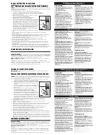
MAGNUM 350 & 350 BIO-Pro System
Quick Setup Guide
1
3
4
2a
Connection
Parts Check
Intake/Outlet
Assembly
TO CHANGE FILTER MEDIA...
Turn off Filter. Turn Flow Regulators on the Disconnect Valves to the closed off position. Disconnect the
valve halves. Lift Canister off motor base and carry to sink. Remove Cover. Change Media. Secure Cover. Return Canister to motor base.
Lock in place by switching base to on. Restart Filter.
04/07 11959
1)
Canister Cover with Intake Diffuser
*
and O-Ring Cover Seal
*
2)
Carbon Media Container w/Lid, Core Set
and Screen
*
3)
Rubber Gaskets
*
4)
Impeller Housing and Exhaust Tube
*
5)
Impeller Assembly
*
6)
Canister, Handle and Sump Cap
*
7)
Motor with On - Off Switch with
Stabilizer Legs - 3
8)
Tube Retainer Bracket
*
9)
Intake Tube with Strainer
*
10)
Outlet Tube with Split Flow Diffuser
*
11)
Hose - 6ft.
12)
Snapper Clamps - 6
13)
Suction Cups - 4
14)
Micron Cartridge and Rigid Core
15)
Rite-Size “V” Bonded Filter Sleeve
16)
Silicon Lubricant
17)
Black Diamond Activated Carbon
18)
Cleaning Brush - Flexible & Rigid
19)
Quick-Disconnect Valves - 2
20)
Intake Extension Tube
CAUTION:
To avoid water spills and leaks, make sure all
hose connections are secured with Snapper Clamps where
indicated.
A.
Attach Intake and Outlet Tubes to Tube Retainer
Bracket. Position the Assembly onto ridge of aquarium
directly above location of Magnum.
Canister Prep
A.
Canister
1.
Unlock Canister from Motor
Base by switching to OFF.
2.
Unclip and remove Cover.
3.
Remove Carbon Media
Container.
(800) 322-1266
B.
Carbon Media Container
1.
Remove Cover and Fill with Black Diamond Carbon.
2.
Replace Cover and rinse thoroughly.
3.
Slide Rite-Size Bonded Filter Sleeve over Container.
4.
Install Container over Impeller Housing and Rubber Gasket.
5.
Install large Rubber Gasket a top Container.
6.
Check top of Exhaust Tube for small Gasket
C.
1.
Replace Canister Cover. Align
Outlet Port and Impeller Exhaust Tube.
2.
Press Cover down and close Clips.
8
*
13
3
*
15
17
11
5
*
A
1
A
2
Remove
Carbon
Media
Container
B
1
B
2
B
3
Rite-Size
Bonded
Filter Sleeve
B
4
Impeller
Housing
Gaskets
B
5
A
3
Tab
Notch
Outlet Port
Impeller
Exhaust Tube
Placement
5
Switch out Carbon Media Container with
Micron Cartridge and Rigid Core.
DO NOT PLUG IN.
NOTE:
Adjust Split Flow Diffuser Diverter.
Hi-Lo Flow
Side-to-Side Flow
A-
1.
Fold hose in half and cut at crease.
Then cut 5” off the ends of each hose.
B.
Plug in power cord. Switch Motor "ON"; wait
10 seconds, then switch "OFF." Aquarium water will
fill Canister to the top, evacuating air through the
Intake Tube. When bubbles stop, switch back to "ON".
B.
Moisten ends of 5” hoses (with hot water or
Silicon Lubricant) and attach to barbs on cover
intake and outlet ports. Using Snapper Clamps,
to lock each hose around the barb fittings.
G.
Extend hoses to highest
barbs on Intake and Outlet
Tubes. Allow for 2 inches of
slack and cut hoses to fit.
Moisten ends of hoses and
attach to Intake and Outlet Tube
barbs. Using Snapper Clamps,
clamp each hose around the
barb fittings.
Barb Fittings
Snapper Clamps
NOTE:
A slight rattling noise is normal ONLY DURING
STARTUP. If noise persists, shut off filter and check for dirt
or debris that may be in bottom of Canister.
NOTE:
Drip Loop
(for safety)
Snapper
Clamps
B.
Extend Stabilizer Legs outward and place
Magnum outside of Aquarium in well-ventilated,
accessible location. Top of Canister must be
below aquarium water level.
2
*
14
Micron Cartridge
Outside
Rigid Core
Inside
Handle
Canister
Motor Base
6
Start Up
STOP:
If assembling Magnum 350 BIO-Pro System,
DO NOT PLUG IN.
Continue on to STEP # 7 for ADDITIONAL connection directives.
A.
Unclip and remove Cover.
Fill Canister half full with water.
Wet O-Ring and place around Cover Skirt.
Replace Cover. Close Cover Clips.
Allow 2”
of slack.
Snapper Clamps
O-Ring
Questions or Missing Parts?
Call Customer Service at:
Cover
Skirt
Clips
2b
Stabilizer
Legs
For Periodic Water Polishing
or Gravel Washing. . .
Tube Retainer
Bracket
*
preinstalled /
*
preassembled
A.
Lock Canister to Motor Base
by switching to On.
NOTE:
Keep
water level above
tube “elbow”
at all times.
Clips
DO NOT PLUG IN.
Outlet Port
Impeller
Exhaust Tube
www.marineland.com
Intake Tube
Outlet Tube
Gaskets
Gaskets
Parts Check
MAGNUM 350 BIO-Wheel Pro System
Cover
BIO-Wheel
Bearings
BIO-Wheel
Assembly
Connector
Clips
Filter Housing
Spray Bar
Sliding Nut
and Screw (L-R)
BIO-Pro 1/2" Hose
#2 Barbed Tee
Connector
#1 Barbed Tee Connector
w/ O-Rings
Spray Bar
O-Rings
5” Hoses
Cut 5”
C.
Disconnect the valve halves
by lifting the lock and twisting.
NOTE:
A straight, clean cut makes installation easier.
D.
Turn back compression nuts on the
two valve halves with locks and press
the long pieces of hose over the valve
barbs. Turn compression nuts to seal
the connection.
E.
Turn back compression nuts on the two
valve halves without locks, and press the
valve barbs onto the 5” hoses. Turn compres-
sion nuts to seal the connection.
F.
Reconnect the valve
halves and slide lock
into place
Lock
Compression Nut
Compression Nut
Flow Regulator
Closed
Off
position
Open
NOTE:
Valve connected to the
Outlet Tube
is used
to regulate water flow.
12
Closed
Lock
Flow Regulator
Closed
Off
position
Lock
Start Up
10
Mount & Placement of Filter Housings
Connection
O-Ring
Coupling Barrel
O-Ring
A.
The BIO-Wheel Pro includes two wheels, each in its own housing. Before
installing, check that both BIO-Wheels rotate freely. Also check that the Spray Bars
are snapped in place with Connector Clips.
B.
Mount each Filter Housing on the back wall of aquarium,
next to Intake and Outlet Tubes and accessible to the
Magnum canister. Replace each Filter Housing cover.
C.
Thread the screws through the sliding nuts on the
Filter Housings. (Left and right nuts are marked. If
nuts have slipped off the housing, reinstall.) Tighten
screws so Filter Housings will not slip.
NOTE:
Remove
Paper insert from
each BIO-Wheel
A.
Connect the Filter Housings with the
#1Barbed Tee Connector
with O-Rings
.
C.
Measure and cut a new piece of
1
/
2
” hose to connect the upper end of
#2 Barbed Tee Connector to the bottom of #1 Barbed Tee Connector.
Secure all connections with Snapper Clamps.
NOTE:
Do not over tighten
B.
Cut hose halfway between the
Outlet Tube and the Disconnect
Valve. Connect the hose attached
to the Outlet Tube to the center of
the #2 Barbed Tee Connector.
Connect the lower end of the #2
Barbed Tee Connector to the hose
attached to the Disconnect Valve.
Spray Bar
Filter Housing Cover
Connector
Clip
Spray
Bar
NOTE:
To remove Spray Bars for
cleaning, push Connector Clips
downward (Don’t Squeeze).
#1 Barbed Tee Connector
with O-Rings
#2 Barbed Tee
Connector
Snapper Clamps
Snapper Clamp
B.
Attach Suction Cup (1) to Outlet Tube.
Moisten Suction Cup and press Outlet Tube
into position on
outside
wall of aquarium.
C.
Attach Suction Cups (2) to Intake Tube.
Moisten Suction Cups and press Intake Tube
into position on
inside
wall of aquarium.
Split Flow
Diffuser Diverter
Suction
Cup
Outside
Wall
Inside Wall
Elbow
Suction Cups
Intake Tube
Outlet Tube
Strainer
CAUTION:
To avoid water spills and leaks,
make sure all hose connections are secured
with Snapper Clamps where indicated.
B.
Plug in power cord. Switch Motor "ON"; wait
10 seconds, then switch "OFF." Aquarium water will
fill Canister to the top, evacuating air through the
Intake Tube. When bubbles stop, switch back to "ON".
NOTE:
A slight rattling noise
is normal ONLY DURING
STARTUP. If noise persists,
shut off filter and check for
dirt or debris that may be
in bottom of Canister.
A.
Unclip and remove Cover.
Fill Canister half full with
water. Wet O-Ring and place
around Cover Skirt. Replace
Cover. Close Cover Clips.
NOTE:
Drip Loop
(for safety)
O-Ring
Cover
Skirt
Clips
Outlet Port
Impeller
Exhaust Tube
Valve Barb
Valve Barb
Snapper Clamps qty.4
Connector
Clip
9
8
7
Additional Quick Setup Guide for
MAGNUM 350 BIO-Pro System
ONLY • Additional Quick Setup Guide for
MAGNUM 350 BIO-Pro System
ONLY • Additional Quick Setup Guide for
MAGNUM 350 BIO-Pro System
ONLY
B
6
Small Gaskets
A-
2.
Then cut 5” off the ends of each hose.
1
/
2
” Hose
Snapper Clamps
#1 Barbed Tee Connector
Outlet Tube
Disconnect
Valve
To Disconnect Valve
To #1 Barbed Tee Connector
To Outlet
Tube
9
*
10
*
16
19
20
*
18
1
*
6
*
7
*
Connector
Clips
3
*
4
*
C
1&2


