


;;;
;
;
;
;
;
;
;
;
;
;;;
;
;
;
;
;
;
;
;;
;;
5
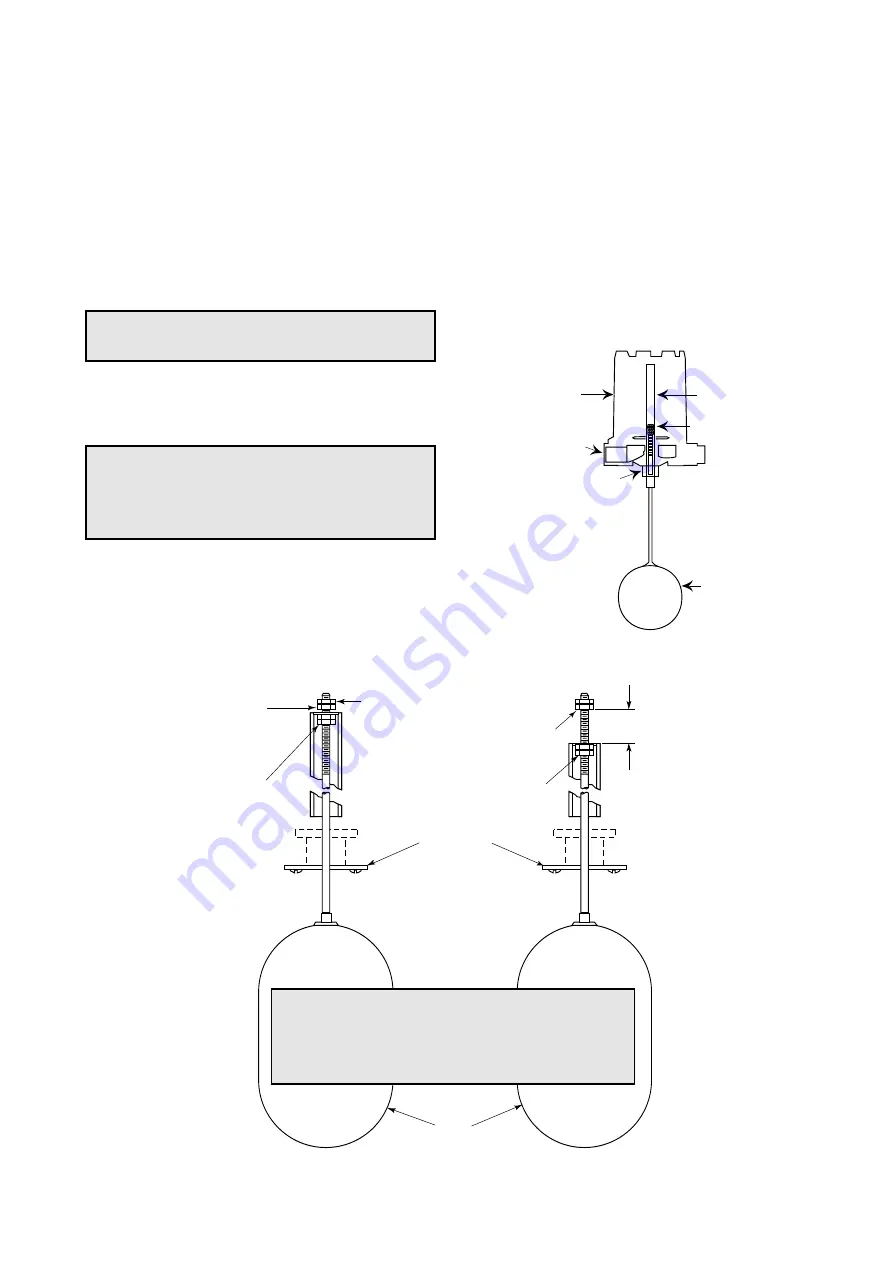
Figure 4
Normal Factory Setting
(minimum differential)
Figure 5
Differential adjustment
Figure 3
SWITCH DIFFERENTIAL ADJUSTMENT
The standard dif
ferential of T20 and T21 Liquid Level
Switches may be field adjusted. Adjustment may be nec-
essary if a wider differential needs to be set to overcome
switch chatter caused by the process.
The differential, or the amount of level travel between
switch-on and switch-off, may be adjusted by repositioning
the lower jam nuts on the float stem. The standard factory
setting is for a minimum amount of play (gap) between the
top jam nuts and the attraction sleeve as shown in
Figure
4
.
NOTE:
For assistance in computing level dif
ferential
change for a specific control, consult the factory giving the
model and serial numbers of the control.
NOTE:
T
o widen the differential 13 mm (0.5"), the lower
jam nuts must be set proportionately lower on the stem (i.e.
in this example 13 mm (0.5")).
1. Determine what change in differential is necessary.
2. Make sure power source is turned off.
3. Unscrew and remove switch housing cover.
4. Disconnect power supply wires from switch mecha-
nism. Pull wires out of conduit connection opening in
housing base. Refer to
Figure 3
.
5a. Perform system shut-down procedures as required to
relieve pressure from tank or vessel and drain off liquid
head, if required. Allow unit to cool.
5b. The amount of level travel between switch-on and
switch-off actuations (differential) may be field adjusted
by repositioning the lower jam nuts on the float stem.
The standard factory setting is for a minimum amount
of play (gap) between the top jam nuts and the attrac-
tion sleeve, as shown in
Figure 4
. This setting may be
increased to a maximum of 13 mm (0.50"), as shown
in
Figure 5
.
6. Remove switch housing assembly by loosening hex
nut, which is located immediately below housing base.
Refer to
Figure 3
.
CAUTION:
Maximum differential adjustment is 13 mm
(0.5").
CAUTION:
Before attempting any work on the control,
pull disconnect switch, or otherwise assure that electri-
cal circuit(s) through the control is deactivated. Close
operating medium supply valve on controls equipped
with pneumatic switch mechanisms.
Switch housing
cover
Slight play (gap)
must be allowed
(0.8 mm (.03") typical)
Position of bottom jam
nuts (normal factory
setting)
For access to bottom jam
nuts, mark position,
remove top jam nuts,
washer, and attracting
sleeve
Maximum gap setting
(Applies to models having
a single switch mechanism
with a single magnet
actuator only)
Replace in
same position
Drop bottom jam nuts to
increase gap setting
(see instructions below)
Sleeve stop
strap
Float
13 mm
(0.50")
Cable connexion
Enclosing tube nut
Enclosing tube
Housing base
Float
Refer to Figures 4 and 5
CAUTION:
After increasing gap setting, be certain to
check for proper operation of switch mechanism by rais-
ing and lowering float assembly. Magnet must snap clean-
ly, with additional float movement available after magnet
snaps.


