background image

19

50-605 Kotron RF Point Model 80/81 Level Switches

3.3

Specifications

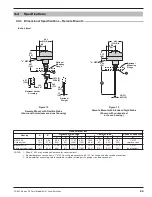
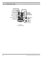
3.3.2 Dimensional Specifications – Integral Mounts

Inches (mm)

2.95

(75)

.

18

75 (5)

.25

00

(

6

)

NEMA 4X/

7

/

9

9.

8

9 (25

1

)

Rotation
Clearance

Op

tional

M

o

u

ntin

g

F

lan

g

e

NEMA 4X/

7

/

9

9.9

1

(25

1

)

2

H

ole

s

.

3

8

(

10

)

D

ia

.

3

.

00

(7

6

)

2.

00

(5

1

)

2.

3

7

(

60

)

3

.5

0

(

8

9)

3

.75

(95)

1

/

2

"

N

PT

(

o

p

t

.)

3

/

4

"

N

PT

(

s

t

d

.)

T

ran

s

d

u

cer

/A

m

p

li

f

ier

Ca

b

le Connection

2

3

G

G

p

l

ugg

e

d

G

p

l

ugg

e

d

G

1

Rotation
Clearance

1

B

A

A

B

Figure 10

Integral Mount with Flexible Probe

(shown with aluminum sand cast housing)

Rotation Clearance

2 H

ole

s

.38 (10) D

ia

.

1

/

2

" NPT

or

3

/

4

" NPT


3.00

(

76

)

2.00

(

5

1)

2.3

7

(

6

0)

3.

5

0

(8

9

)

3.

7

5

(

9

5

)

F

B

A

E

Op

tional

M

o

u

ntin

g

F

lan

g

e

.

5

0 (13)

.

6

2

5

(1

6

)

C

B

A

D

Rotation
Clearance

G

2

1

1

I

.

L

.

3

G

Figure 11

Integral Mount with Standard Rigid Probe

(shown with carbon steel housing)

Summary of Contents for STI Kotron 80

Page 1: ...Installation and Operating Manual Kotron Model 80 81 RF Point Level Switches...

Page 2: ...uipment may be impaired WARNING Explosion hazard Do not connect or disconnect equipment unless power has been switched off or the area is known to be non hazardous Notice of Trademark Copyright and Li...

Page 3: ...2 7 2 Remote Mount Models 9 2 7 2 1 Probe Preamplifier Wiring 9 2 7 2 2 Relay Wiring 10 2 7 2 3 Power Wiring 10 2 7 3 Relay Wiring Chart 10 2 7 4 Wiring Notes and Definitions 11 2 8 Calibration 11 2 8...

Page 4: ...tank the amount of capaci tance developed between the sensing probe and the ground also rises and falls This change in capacitance is sensed by the electronics The capacitance controlled oscillator ci...

Page 5: ...bove 160 F 71 C Special pre caution should be made to prevent exposure to corrosive atmosphere excessive vibration shock or physical damage It is common practice to use the metal tank wall as the refe...

Page 6: ...r use with non conductive liquids as only approximately 0 625 of level change is required to com pletely cover or uncover the probe Horizontally mounted probe rods should be installed so that the rod...

Page 7: ...ing 12 inches 305 mm in length are shipped pre assembled Units with probes over 12 inches 305 mm in length are shipped unassembled to avoid damage during transit They must be assembled before mounting...

Page 8: ...g steps 7 through 11 7 Loosen both socket clamp screws 8 Pull clamp and Teflon retaining bushing off probe 9 While holding probe cable loosen upper probe nut 10 Pull excess cable up through probe nuts...

Page 9: ...e probe Refer to Figure 8 4 Screw housing on probe until hand tight Housing can be wrench tightened to align conduit connection with con duit Proceed to Section 2 7 Wiring on page 8 2 5 4 Remote Mount...

Page 10: ...t to mounting nut 6 Screw mounting nut into tank bushing until tight Caution Apply wrench to lower probe nut only NOTE Do not allow the probe to fall in the tank while following steps 7 through 11 7 L...

Page 11: ...e a grounding wrist strap when installing and removing circuit boards A grounded workstation is also recommended 3 Handle printed circuit boards only by the edges Do not touch components or connector...

Page 12: ...tion Screw Refer to Figure 6 on page 4 2 7 2 1 Probe Preamplifier Wiring 1 Strip approximately 75 inch of outer jacket insulation from each end of the conductor 2 At the probe preamplifier end twist t...

Page 13: ...r replacement of housing cover Caution Observe all applicable electrical codes and proper wiring procedures 5 Replace housing cover 6 Power up unit and proceed with calibration of instrument as descri...

Page 14: ...n is made between common COM and the normally closed NC and there is no connection between common COM and the normally open NO terminals 7 When the relay coil is energized a connection is made between...

Page 15: ...vel were at or above the set point 2 8 2 2 Low Level Mode In this mode an electrical power failure will de energize the relay causing the contacts to assume a position as if product level were at or b...

Page 16: ...unterclockwise CCW until LED indicator goes off the relay will change state then turn the control slowly in the CW direction until the LED indicator again comes on Repeat this on off procedure several...

Page 17: ...ator turns ON The relay will change state and the wide differential span is now calibrated Do not change setting after LED is ON NOTE A second span adjustment check can be made by moving the span adju...

Page 18: ...available If the resistance measures infinity the probe is operating correctly If the resistance measures less than infinity there may be a problem with the probe Call the factory for additional assi...

Page 19: ...mplifier board 6 Turn on power to the unit 7 The red LEDs will be off Adjust the narrow differential point potentiometer s counterclockwise until the LED s turn on Then slowly adjust each potentiomete...

Page 20: ...obe range jumper switch to the low level position Refer to Figure 12 on page 20 The LED will turn off If not turn the span potentiometer slowly coun terclockwise until the LED turns off Refer to Figur...

Page 21: ...20 VAC 10 15 50 60 Hz Supply voltage 240 VAC 10 15 50 60 Hz 24 VDC 10 Power consumption 7 watts maximum Zero range 0 pF minimum 3000 pF maximum High range 4 pF minimum Differential range 1500 pF maxim...

Page 22: ...0 89 3 75 95 1 2 NPT opt 3 4 NPT std Transducer Amplifier Cable Connection 2 3 G G plugged G plugged G 1 Rotation Clearance 1 B A A B Figure 10 Integral Mount with Flexible Probe shown with aluminum s...

Page 23: ...m overhead clearance for cover removal Standard process connection is 3 4 NPT Consult probe brochure 50 125 for flange and other probe connections Probe amplifier connecting cable should be shielded t...

Page 24: ...ed Operating Relay Amplifier Assembly LED Indicator CM2 Fail safe Mode Selection Switch 120 240 VAC input 50 60 HZ 24 VDC input Typical DPDT control relay Each terminal screw is identified on the term...

Page 25: ...ifier PC board single point 30 2082 001 4 Housing cover NEMA 4X carbon steel 89 6510 003 NEMA 4X 7 9 aluminum 89 6554 001 5 O ring NEMA 4X for carbon steel cover 12 1318 001 NEMA 4X 7 9 for aluminum c...

Page 26: ...NTING CONFIGURATION 0 Integral 1 Remote HOUSING 52 NEMA 4X carbon steel 3 4 NPT single conduit 80 NEMA 4X 7 9 aluminum 3 4 NPT dual conduit single point models NUMBER OF SET POINTS 12 Single point ala...

Page 27: ...50 605 Kotron RF Point Model 80 81 Level Switches 24 NOTES...

Page 28: ...eplacement parts or in extreme cases a complete new control to replace the original equipment before it is returned If this is desired notify the factory of both the model and serial numbers of the co...

Reviews: