50-605 Kotron RF Point Model 80/81 Level Switches
10
2.7.2.2 Relay Wiring
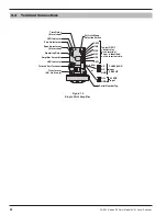
Refer to Section 2.7.3,
Relay Wiring Chart
for different
relay wiring options. Refer to Section 3.4,
Terminal
Connections
on page 21 for terminal locations.
2.7.2.3 Power Wiring
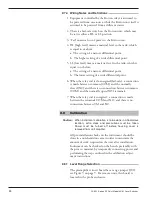
1. Make sure power source is turned off.
2. Pull power supply wires through conduit connection.
Refer to Figure 8 on page 6.
3. Connect AC power to AC(+), AC(–) and GND terminals.
Connect DC power to DC(+) and GND terminals.
Refer to Section 3.4,
Terminal Connections
on page 21.
4. Dress the wires together neatly and securely with cable
ties. Be certain that adequate clearance exists for
replacement of housing cover.
Caution:
Observe all applicable electrical codes and proper wiring
procedures.
5. Replace housing cover.
6. Power up unit and proceed with calibration of instrument
as described in instructions following.
NOTE: Be certain to route all power and control wires through con-
duit outlet only and run probe wire up through center hole in
amplifier housing base. Supply voltage and signal wires
should not
be run in the same conduit.
2.7.3 Relay Wiring Chart
Kotron
Power
Material
Level
Fail-safe
Position
Relay Coil
Relay Terminal
COM to NC COM to NO
On
High
HL
De-energized
Closed
Open
LL
Energized
Open
Closed
Low
HL
Energized
Open
Closed
LL
De-energized
Closed
Open
OFF
(Fail)
High
HL
De-energized
Closed
Open
LL
De-energized
Closed
Open
Low
HL
De-energized
Closed
Open
LL
De-energized
Closed
Open

