


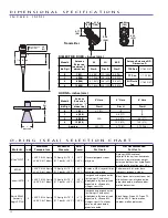


The PULSAR Model R96 Radar transmitter can be mounted
on a vessel using a variety of process connections.
Generally either a threaded or flanged connection is used.
L O C A T I O N
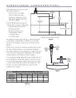
Ideally, the Radar transmitter should be mounted
1
⁄
2
radius
from center of the tank providing an unobstructed signal
path to the liquid surface where it should illuminate (with
microwave energy) the largest possible surface area. Do
not install in center of tank top or within 18 inches (45 cm)
of tank wall. Tank walls may produce reflections that
must be minimized during field configuration (Antenna
Orientation). Refer to Figure 7.
B E A M A N G L E
The various antenna designs exhibit different beam
patterns. Figure 9 shows the beam spread for all PULSAR
antennas. Ideally the beam pattern should illuminate the
maximum liquid surface with a minimum striking other
objects in the vessel including the tank wall. Use these
drawings to determine the optimum installation location.
O B S T R U C T I O N S
Almost any object that falls within the beam pattern will
cause reflections that may be misinterpreted as a false
liquid level. Although the PULSAR Model R96 has a pow-
erful Echo Rejection routine, all possible precautions
should be taken to minimize false target reflections with
proper installation and orientation. Refer to Figures 8 & 9.
1/2
Radius
>18"
(>45 cm)
D
W
W
∝
∝
Beam Spread, W @-3dB; ft (m)
Antenna
Beam Angle
(
∝
)
Dielectric Rod
25°
4" Horn
25°
6" Horn
17°
Distance, D
10 (3)
4.5 (1.4)
3.0 (1.0)
20 (6)
8.9 (2.7)
6.0 (1.8)
30 (9)
13.3 (4.1)
9.0 (2.7)
40 (12)
17.8 (5.4)
12.0 (3.7)
50 (15)
22.2 (6.8)
15.0 (4.6)
60 (18)
26.6 (8.1)
18.0 (5.5)
65 (20)
28.9 (8.8)
19.5 (6.0)
98 (30)
*
29.3 (9.0)
130 (40)
*
39.0 (12.0)
Figure 7
M O U N T I N G
Figure 8
Figure 9
4
*Dielectric rod and 4" horn not recommended beyond 65 feet (20 meters).


