background image

5

57-651 Eclipse

®

SIL Certified Safety Manual for Enhanced Model 705-51AX-XXX

2.2

Miscellaneous Electrical Considerations

The following are miscellaneous electrical items that must
be considered in any installation:

2.2.1 Pollution Degree 2

The Enhanced ECLIPSE Model 705 is designed for use in
Category II, Pollution Degree 2 installations.

The usual pollution degree used for equipment being evalu-
ated to IEC/EN 61010 is a nonconductive pollution of the
sort where occasionally a temporary conductivity caused by
condensation is expected.

2.2.2 Overvoltage

The Enhanced ECLIPSE Model 705 has over-voltage protec-
tion per the necessary CE requirements. As this protection is
up to 1KV when considering Hi-pot, Fast Transients and
Surge, no unsafe failure modes should exist up to this potential.

Overvoltage Category II is a local standard, covering appli-
ances, portable equipment, etc., with smaller transient volt-
ages than those characteristic of Overvoltage Category III.
(This category applies from the wall plug to the power-sup-
ply isolation barrier or transformer).

The typical industrial plant environment is Overvoltage
Category II, therefore, most equipment evaluated to the
requirements of IEC/EN 61010 is considered to belong in
this classification.

3.0

Mean Time To Repair (MTTR)

SIL determinations are based on a number of factors,
including the Mean Time To Repair (MTTR). The analysis
for the Enhanced ECLIPSE Model 705 is based on a
MTTR of 24 hours.

4.0

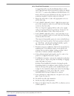
Supplemental Documentation

The Enhanced ECLIPSE Model 705 Installation and
Operating Manual (57-600) must be available and used for
installation of the level transmitter.

If the HART digital protocol will be used, the following
Electronic Device Description Files are also required:

Manufacturer Code 0x56
Model 705 3.x Device ID 0xE5, device revision 2,
DD revision 2.

For device installations in a classified area, the relevant safety
instructions and electrical codes must be followed.


Summary of Contents for Eclipse 705-51A Series

Page 1: ...omer specified out of range signal i e less than 3 8 mA or greater than 20 5 mA The Enhanced Model 705 is certified for use in low or high demand level measurement applications Application The Enhance...

Page 2: ...l Level of Personnel 6 5 3 Necessary Tools 6 5 4 Storage 7 5 5 Installation 7 5 6 Configuration 7 5 6 1 General 7 5 6 2 SIS Configuration Requirements 8 5 6 3 Write Protecting Locking 8 5 7 Site Accep...

Page 3: ...ssified as a Type B Device as defined by IEC61508 NOTE Please ensure that the Model 705 transmitter and probe are installed as a set matched by the Serial Number shown on the name plates 1 3 Determini...

Page 4: ...This SIL 2 3 certified device is only available with an analog signal 4 20 mA with HART digital communications The measurement signal used by the logic unit must be the generated analog 4 20 mA signa...

Page 5: ...equipment etc with smaller transient volt ages than those characteristic of Overvoltage Category III This category applies from the wall plug to the power sup ply isolation barrier or transformer The...

Page 6: ...ildup on the probe Refer to Section 3 3 3 of Installation and Operating Manual 57 600 for more detailed application information regarding media buildup and bridging 5 1 2 Environmental Refer to Sectio...

Page 7: ...nd resetting of the password protection function Section 2 6 5 1 of I O Manual 57 600 provides menu selec tion items for configuration of the transmitter as a Level Only sensing device See Section 5 6...

Page 8: ...eplate MEASUREMENT TYPE Level Only LEVEL UNITS As indicated on probe nameplate PROBE LENGTH As indicated on probe nameplate LEVEL OFFSET As required by application DIELECTRIC As required by applicatio...

Page 9: ...ete a site acceptance test should be performed to ensure proper opera tion This procedure is identical to the Proof Test Procedure described in Section 6 1 4 of this manual Record the results for futu...

Page 10: ...in the Safety Integrity Level of a Safety Instrumented System it is imperative that specified manual proof testing be completed at the time intervals specified The user must select the type of inspect...

Page 11: ...level from the probe The Status parameter should say Dry Probe and the level reading should be equal to the value in the Level Offset parameter 5 Perform a two point calibration check of the transmit...

Page 12: ...ilistic calculation method is meaningless as the probability of failure significantly increases with time The useful lifetime is highly dependent on the component itself and its operating conditions t...

Page 13: ...endently verify all changes to end user configured parameters and validate the safety functionality prior to reliance on the product for safety protection End user s responsibility SSA 8 The end user...

Page 14: ...14 57 651 Eclipse SIL Certified Safety Manual for Enhanced Model 705 51AX XXX 8 2 FMEDA Report exida Management Summary...

Page 15: ...15 57 651 Eclipse SIL Certified Safety Manual for Enhanced Model 705 51AX XXX...

Page 16: ...al Procedure So that we may efficiently process any materials that are returned it is essential that a Return Material Authorization RMA number be obtained from the factory prior to the material s ret...

Reviews: