3
WIRING
USER INTERFACE
TIME
DELA
Y
AS
I +
AS
I –
FA
U
LT
MOD
EL 96
0
POWER
WET
DI
A
GN
OSTIC
LE
V
EL
TEST
MALF
.
TEST
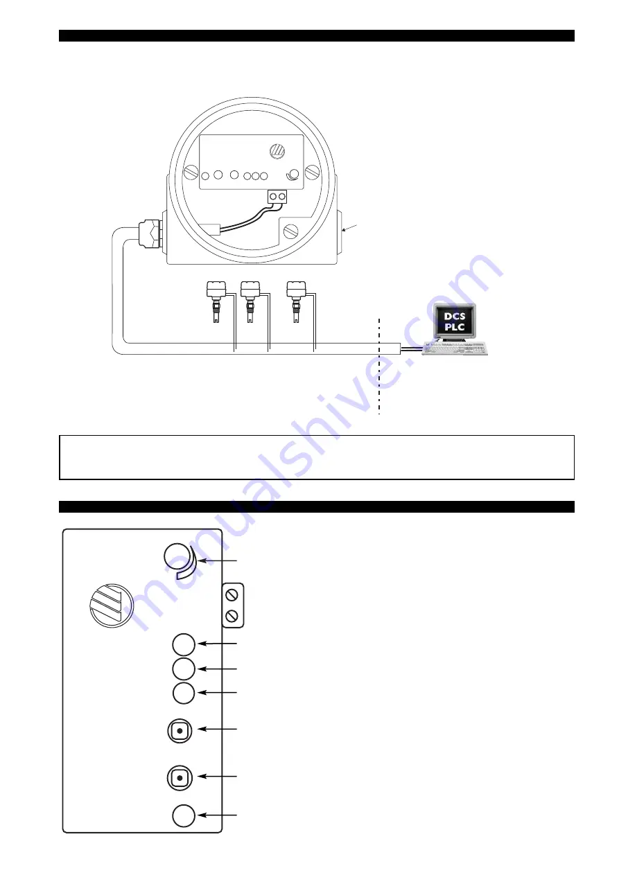
Standard unshielded
2-wire cable
Up to 31 units (slaves) / 62 units (in the
extended addressing mode) on one net-
work
M12 x 1 AS-i bus quick
disconnect male connector
or cable gland
Adjustable time delay: 1 to 45 s. Time delay is typically used where turbulence,
boiling or splashing can cause false level alarms
AS-i wiring terminals
Plugged entry
HAZARDOUS AREA
SAFE AREA
Echotel
®
960 electronics
Important: In extended addressing mode, the A or B channel select must be programmed as well. Model 960
units are factory configured as unassigned slaves with the address defaulted to 0. The address must be
changed by the end user via programming at the PLC or with special handheld addressing devices.
TIME
DELAY
ASI +
ASI –
FAU LT
MO
D
EL
960
POWER
WET
DIAGNOSTIC
LEVEL
TEST
MALF.
TEST
Red fault LED: ON = AS-i communication fault,
FLASHES when an instrument failure is detected
(red Diagnostic LED is ON)
Green power LED: ON = power is on
Yellow wet LED: ON = sensor gap is immersed
Pushbutton for testing alarm output signal: D2 = 1 means immersed gap
D2 = 0 means dry gap
Pressing pushbutton causes D2 to change state
Pushbutton for testing malfunction output. Pressing pushbutton (min 8-10 s)
causes a malfunction:
«FAULT»
LED flashes and
«DIAGNOSTIC»
LED is ON
Red diagnostic LED: ON = unit malfunction
FLASHES when activating troubleshooting
(see troubleshooting section)
Summary of Contents for ECHOTEL 960
Page 11: ...11 ...


