


6
SWITCH DIFFERENTIAL ADJUSTMENT (cont.)
PREVENTIVE MAINTENANCE
NOTE: Use a new enclosing tube gasket when reassem-
bling enclosing tube to the chamber. Coat enclosing tube
threads with “anti-seizing” compound.
13. Replace enclosing tube, switch, and base on chamber.
Screw tube clockwise until tightened to 10,42 -
13,90 kgm of torque.
14. Rotate switch housing to correct position and tighten
set screw at base of switch housing. See Figure 4.
15. Bring supply wires through conduit outlet. Follow steps
5 through 10 of the “Wiring” section on page 4.
NOTE: If switch mechanism fails to function properly, check
vertical alignment of control housing and consult
installation bulletin on switch mechanism. If the unit still
fails to function properly, consult the factory.
HIGH LEVEL CONTROLS
On high level controls, the switch trips on the higher actua-
tion point and resets on the lower actuation point.
CAUTION:
On high level controls, widening the differential
requires raising the trip point a proportionate
amount. The reset point will remain the same.
To widen the differential by raising the trip point, follow
steps 1 through 16 under “Low Level Controls”.
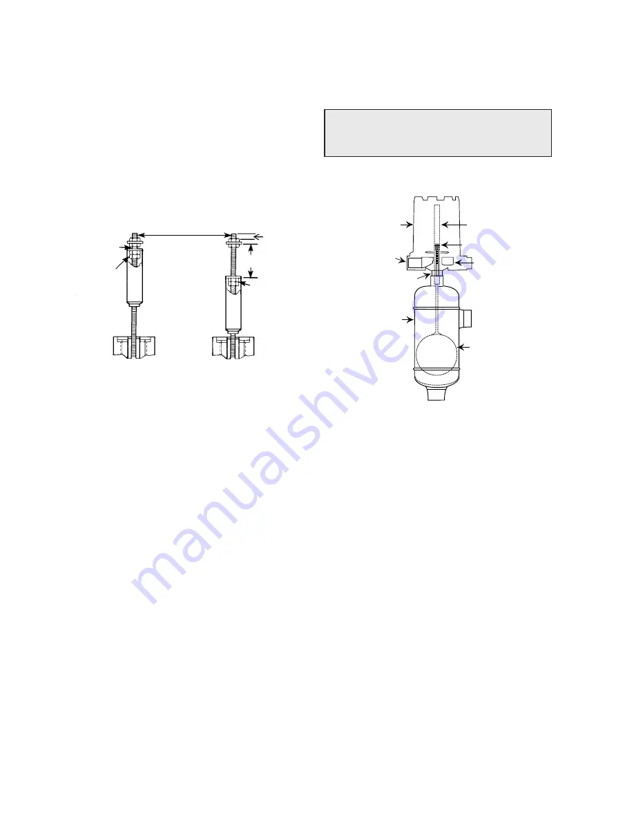
Switch
housing
cover
Conduit
connection
Enclosing
tube nut
Enclosing tube
See figures 6 and 7
Housing base
Float
Chamber
Figure 5
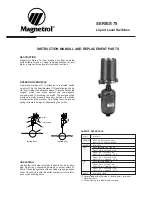
Slight play (gap)
must be allowed
(0.8 (0.03") typical
Position of bottom
jam nuts (normal
factory setting)
Replace in same position
Distance
Drop bottom
jam nuts to
increase gap
setting (see
instructions
above)
Maximum gap setting
(applies to models having
a single switch mecha-
nism with a single magnet
actuator only!)
CAUTION: After increasing
gap setting, be certain to
check for proper operation of
switch mechanism by raising
and lowering float assembly.
Magnet must 'snap' cleanly
with additional float movement
available after magnet snaps.
25 (1")
Normal factory setting
(minimal differential)
Figure 6
Differential adjustement
Figure 7
Periodic inspections are a necessary means to keep your Magnetrol level control in good working order. This control
is, in reality, a safety device to protect the valuable equipment it serves. Therefore, a systematic program of "preven-
tive maintenance" should be implemented when control is placed into service. If the following sections on "what to
do" and "what to avoid" are observed, your control will provide reliable protection of your capital equipment for many
years.
WHAT TO DO
1. Keep control clean
NEVER leave switch housing cover off the control. This
cover is designed to keep dust and dirt from interfering
with switch mechanism operation. In addition, it protects
against damaging moisture and acts as a safety feature
by keeping bare wires and terminals from being
exposed. Should the housing cover become damaged or
misplaced, order a replacement immediately.
2. Inspect switch mechanisms, terminals and connec-
tions monthly.
– Mercury switches may be visually inspected for short
circuit damage. Check for small cracks in the glass
tube containing the mercury. Such cracks can allow
entrance of air into the tube causing the mercury to
"oxidize". This is noticeable as the mercury will appear
dirty and have a tendency to "string out" like water,
instead of breaking into round pools. If these condi-
tions exist, replace the mercury switch immediately.
– Dry contact switches should be inspected for exces-
sive wear on actuating lever or misalignment of
adjusting screw at point of contact between screw
and lever. Such wear can cause false switch actuat-
ing levels. Adjust switch mechanism to compensate
(if possible) or replace switch.
Do NOT operate your control with defective or malad-
justed switch mechanisms (refer to bulletin on switch
mechanism furnished for service instructions).
– Magnetrol controls may sometimes be exposed to
excessive heat or moisture. Under such conditions,
insulation on electrical wires may become brittle,
eventually breaking or peeling away. The resulting
"bare" wires can cause short circuits.
Check wiring carefully and replace at first sign of brittle
insulation.
– Vibration may sometimes cause terminal screws to
work loose. Check all terminal connections to be cer-
tain that screws are tight. Air (or gas) operating medi-
um lines subjected to vibration may eventually crack
or become loose at connections causing leakage.
Check lines and connections carefully and repair or
replace, if necessary.
– On units with pneumatic switches, air (or gas) operat-
ing medium lines subjected to vibration, may eventu-
ally crack or become loose at connections carefully
and repair or replace, if necessary.
NOTE: As a matter of good practice, spare switches should
be kept on hand at all times.
3. Inspect entire unit periodically
Isolate control from vessel. Raise and lower liquid level
to check for switch contact and reset.
Summary of Contents for 075
Page 13: ...13 ...


