Magnetrol 075 Instruction Manual Download Page 1

SERIES 75

Liquid Level Switches

®

INSTRUCTION MANUAL AND REPLACEMENT PARTS

DESCRIPTION

Magnetrol’s Series 75 level switches are float operated
units suitable for use on clean liquid applications for level
alarm, pump control and safety shutdown functions.
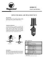
OPERATING PRINCIPLE

A permanent magnet 

is attached to a pivoted switch

actuator 

. As the float/ displacer 

rises following the liq-

uid level, it raises the attraction sleeve 

into the field of the

magnet, which then snaps against the non-magnetic
enclosing tube 

, actuating the switch. The enclosing tube

provides a static pressure boundary between the switch
mechanism and the process. On a falling level, an inconel
spring retracts the magnet, deactivating the switch.

Rising level

Falling level

pivot

return spring

UNPACKING

Unpack the instrument carefully. Inspect all units for dam-
age. Report any concealed damage to carrier within 24
hours. Check the contents of the packing slip and purchase
order. Check and record the serial number for future refer-
ence when ordering parts.

AGENCY APPROVALS

Agency

Approval  

CENELEC

EEx d 

II

C T6, explosion proof

EEx ia 

II

C T6, intrinsically safe

BASEEFA

Ex d 

II

C T6

CSA

Non-Hazardous CSA Type 4X

Class 

I

, Div. 2, Groups B, C & D

Class 

I

, Div. 1, Groups C & D

Class 

II

, Div. 1, Groups E, F & G

Class 

I

, Div. 1, Groups B, C & D

Class 

II

, Div. 1, Groups E, F & G

FM

Non-Hazardous NEMA  4X

Class 

I

, Div. 1, Groups C & D

Class 

II

, Div. 1, Groups E, F & G

Class 

I

, Div. 1, Groups B, C & D,

Class 

II

, Div. 1, Groups E, F & G

SAA 

Ex d 

II

C T6  (IP65)

Not available with all switches; Consult factory for proper
model numbers.

Consult factory for proper model numbers.

Summary of Contents for 075

Page 1: ...eactivating the switch Rising level Falling level pivot return spring UNPACKING Unpack the instrument carefully Inspect all units for dam age Report any concealed damage to carrier within 24 hours Check the contents of the packing slip and purchase order Check and record the serial number for future refer ence when ordering parts AGENCY APPROVALS Agency Approval CENELEC EEx d IIC T6 explosion proo...

Page 2: ...pecific gravity Pressure rating Models with material construction code bar C PSIG F 4 40 C 230 C 400 C 100 F 450 F 750 F A 0 65 42 7 29 0 25 2 620 420 365 B 0 75 69 0 58 6 51 7 1000 850 750 C 0 60 34 5 22 4 19 6 500 325 285 G 0 57 51 7 38 6 32 7 750 560 475 P 0 75 27 6 17 9 15 5 400 260 225 O 0 85 27 6 22 4 19 6 400 325 285 MATERIALS OF CONSTRUCTION SIZE AND TYPE OF TANK CONNECTIONS see configurat...

Page 3: ... 2 EEA E1A EZ8 EOD EO8 EY8 EO7 EY7 EEB E1B EZ7 EOM EO6 EY6 EO5 EY5 Series 2 400 C 1 2AA 22A 23A 2KD 2K8 2U8 2K7 2U7 2AB 22B 23B 2KM 2K6 2U6 2K5 2U5 Vibr resistant 750 F SPDT 2 2BA 24A 25A 2LD 2L8 2V8 2L7 2V7 2BB 24B 25B 2LM 2L6 2V6 2L5 2V5 mercury switch 3 2CA 26A 27A 2MD 268 278 267 277 2CB 26B 27B 2MM 266 276 265 275 with DPDT 1 2DA 28A 29A 2ND 2N8 2X8 2D7 2W7 2DB 28B 29B 2NM 2N6 2X6 2D5 2W5 bea...

Page 4: ...ore responsive and accurate level change in the control Liquid in a long line may be cooler and more dense than liquid in the vessel causing lower level indication in the control than actual level in the vessel Most mechanical control switch housings are designed to allow 360 positioning of the cable entries by loosening the set screw s See figure 4 On high temperature applica tions above 120 C 25...

Page 5: ... 5 5 Perform system shut down procedures as required to relieve pressure from float chamber of control Allow unit to cool a Close shut off valves if so equipped to isolate control from tank Drain off liquid in float chamber See Figure 3 on page 4 b On installations without shut off valves relieve pressure from the tank Drain liquid in tank to a level below the connections of the float chamber NOTE...

Page 6: ...avoid are observed your control will provide reliable protection of your capital equipment for many years WHAT TO DO 1 Keep control clean NEVER leave switch housing cover off the control This cover is designed to keep dust and dirt from interfering with switch mechanism operation In addition it protects against damaging moisture and acts as a safety feature by keeping bare wires and terminals from...

Page 7: ...in two place 90 apart Refer to Figure 3 on page 4 7 If mechanism is equipped with a mercury switch examine glass mercury tube closely as previously described in Preventive Maintenance section If switch is damaged replace it immediately 8 If switch mechanism is operating satisfactorily proceed to check sensing unit CHECK SENSING UNIT 1 Check to be certain liquid is entering float chamber A valve ma...

Page 8: ... 05 B75 47 1 88 67 2 63 C75 41 1 61 64 2 51 G75 38 1 50 58 2 28 P75 36 1 41 60 2 36 Part n mm inches code HL LL A75 25 0 98 52 2 05 B75 59 2 31 79 3 11 C75 53 2 08 76 3 00 G75 46 1 88 66 2 60 P75 48 1 88 72 2 83 Part n mm inches code HL LL A75 25 0 98 52 2 05 B75 76 3 00 96 3 77 C75 70 2 77 93 3 63 G75 64 2 50 84 3 30 075 75 2 94 103 4 05 P75 65 2 56 89 3 50 1 and NW 25 DIN connections NPT flanged...

Page 9: ...EMA 7 9 1 NPT F entry BASEEFA CENELEC M20 x 1 5 or 3 4 NPT F entry Pneumatic switches K Series Nema 3R 1 4 NPT F two entries J Series Nema 3R 1 4 NPT F one entry Rotation clearance L NEMA 4X IP 65 109 4 29 NEMA 7 9 100 3 94 BASEEFA CENELEC 110 4 33 Pneumatic K NEMA 3R 130 5 12 Pneumatic J NEMA 3R 110 4 33 All housings rotatable 360 Allow 200 mm 7 87 overhead clearance for cover removal Threaded so...

Page 10: ... 356 230 733 P75 217 84 573 224 93 580 356 200 712 356 200 712 inches 1 1 2 NPT 1 1 2 socket weld 1 1 2 or NW 40 1 1 2 or NW 40 Flanged upper side bottom Flanged side side Part n code A B C max A B C max D E F max G H J max A75 8 74 3 30 23 80 8 74 3 66 23 80 14 7 87 29 05 14 7 87 29 05 B75 8 56 3 88 23 00 8 84 4 25 23 30 14 8 46 28 46 14 8 46 28 46 C75 8 56 3 88 23 00 8 84 4 25 23 30 14 8 46 28 4...

Page 11: ...units only with all parts listed under items 4 through 10 assembled When ordering specify model serial number of control Item Description Models with mat l code 4 A B C G J O P75 1 Housing cover Housing Refer to bulletin 42 780 for switch housing cover and base assemblies 2 Housing base kits 3 Switch mechanism Refer to bulletin on switch mechanism furnished listed on page 4 4 Jam nuts 5 Guide wash...

Page 12: ...odels in the field Switch actuation levels have been set at the factory to meet specific customer specifications Variations in actual conditions from design conditions usually requires special control modifications Consult the factory or your local representative for assistance REPLACEMENT OF FLOAT AND STEM ASSEMBLIES Should replacement of either upper or lower float and stem assembly be required ...

Page 13: ...13 ...

Page 14: ...E So that we may efficiently process any materials that are returned it is essential that a Return Material Authorisation RMA form will be obtained from the factory It is mandatory that this form will be attached to each material returned This form is avail able through Magnetrol s local representative or by contacting the factory Please supply the following information 1 Purchaser Name 2 Descript...

Reviews: