


Section 6 – Installation Diagrams (Continued)
Telemotive Laser Guard Instruction Manual – October 2009
19
2
.0
A
R
E
D
W
IR
E
B
L
A
C
K
W
IR
E
G
R
E
E
N
W
IR
E
C
U
T
F
O
IL
A
T
J
A
C
K
E
T
B
L
A
C
K
T
W
IS
T
E
D
P
A
IR
1
R
E
D
T
W
IS
T
E
D
P
A
IR
1
B
L
A
C
K
T
W
IS
T
E
D
P
A
IR
2
R
E
D
T
W
IS
T
E
D
P
A
IR
2
(C
U
S
T
O
M
E
R
T
O
I
N
S
T
A
L
L
)
L
A
S
E
R
C
O
N
T
R
O
L
C
A
B
L
E
D
R
A
IN
W
IR
E
R
E
D
W
IR
E
B
L
A
C
K
W
IR
E
J
2
J
1
P
O
W
E
R
S
U
P
P
L
Y
M
O
D
U
L
E
(A
1
2
1
6
0
-2
0
2
)
B
L
A
C
K
W
IR
E
R
E
D
W
IR
E
P
O
W
E
R
S
U
P
P
L
Y
(E
1
0
1
8
6
-1
)
R
E
D
W
IR
E
B
L
A
C
K
W
IR
E
G
R
E
E
N
W
IR
E
(C
U
S
T
O
M
E
R
T
O
I
N
S
T
A
L
L
)
C
O
N
T
R
O
L
O
U
T
P
U
T
S
2ND
1ST
FAUL
T
3RD
COM
COM
COM
NC
NO
NC
NO
COM
NC
NO
NC
NO
R
A
N
G
E
D
E
T
E
C
T
O
R
M
O
D
U
L
E
(E
1
4
0
0
1
-0
)
P
O
W
E
R
I
N
P
U
T
(C
U
S
T
O
M
E
R
T
O
I
N
S
T
A
L
L
)
COM
J
1
NC
NO
COM
NO
COM
NC
NC
NO
NC
NO
COM
1ST
2ND
FAU
LT
3RD
J1
COM
NC
COM
NO
NO
COM
NC
NC
NC
NO
COM
NO
1ST
2ND
FAU
LT
3RD
2
.0
A
G
N
H
N
G
H
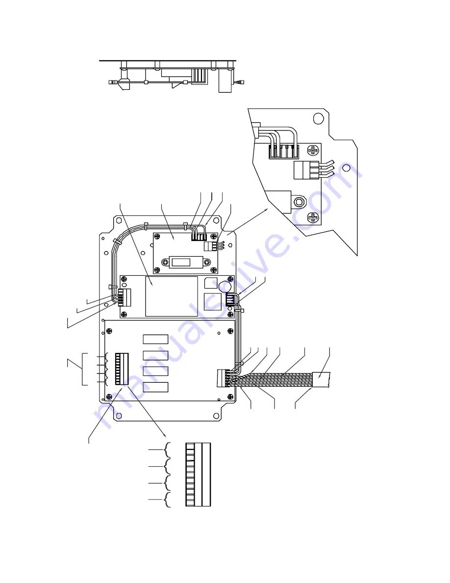
Figure 6-4. Laser Support Unit E
14001-0 Board Wiring (110 VAC Unit)


