Interconnections
30
Encoder
The HPV 900 Series 2 can be configured for
an incremental two-channel quadrature
encoder. The drive’s encoder circuitry
incorporates resolution multiplication and
complimentary outputs. It is recommended that
a diferential line driver encoder of type 7272 is
used. Push-pull type encoders can be used but
only for TerMag boards at 46S04284-1020.
See appendix Selecting and Mounting of
Encoder page 187.
Incremental Encoder Wiring
Use twisted pair cable with shield tied to
chassis ground at drive end, in order to
minimize magnetic and electrostatic pick-up
current and to minimize radiated and
conducted noise.
Reasonable care must be taken when
connecting and routing power and signal
wiring. Radiated noise from nearby relays
(relay coils should have R/C suppressors),
transformers, other electronic drives, etc. may
be induced into the signal lines causing
undesired signal pulses.
Power leads and signal lines must be routed
separately. Signal lines should be shielded,
twisted and routed in separate conduits or
harnesses spaced at least 12 inches apart
from power wiring. This protects the cable from
physical damage while providing a degree of
electrical isolation. Also, do not run cable in
close proximity to other conductors, which
carry current to heavy loads such as motors,
motor starters, contactors, or solenoids. Doing
so could result in electrical transients in the
encoder cable, which can cause undesired
signal pulses. Power leads are defined as the
transformer primary and secondary leads,
motor leads and any 120 VAC or above control
wiring for relays, fans, thermal protectors, etc.
Continuity of wires and shields should be
maintained from the encoder through to the
controller avoiding the use of terminals in a
junction box. The shield and shield drain wires
must be insulated from other objects. This
helps to minimize radiated & induced noise
problems and magnetically induced ground
loops.Always use an encoder with
complementary output signals. Connect with
twisted-pair shielded wire so that wire-induced
currents will self-cancel.
NOTE: DO NOT ground the encoder through
both the machine and the cable wiring.
Connect the shield at the receiver device only.
If the shield is connected at both ends, noise
currents will flow through the shield and
degraded performance will result. HPV 900
Series 2 Incremental Encoder Specifications
The HPV 900 Series 2 requires the use of an
encoder coupled to the motor shaft. The
encoder power can be either a 5VDC or
12VDC supply. The capacity of each power
supply is the following:
supply voltage:
12VDC
200mA capacity
supply voltage:
5VDC
400mA capacity
The HPV 900 Series 2 can accept encoder
pulses of:
500 to 10,000 pulses per revolution (ppr)
a maximum frequency of 300kHz
IMPORTANT
Motor phasing should match the encoder
feedback phasing. If the phasing is not
correct, the motor will not accelerate up to
speed. It will typically oscillate back and forth
at zero speed, and the current will be at the
torque limit. Swapping A and /A or switching
two motor phases should correct this situation.
The encoder pulses per revolution must be
entered in the ENCODER PULSES parameter,
see Drive A1 Submenu on page 40
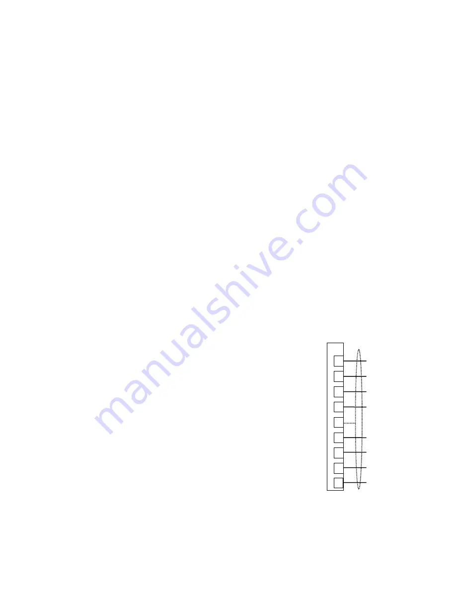
The encoder connection terminals are shown
in Figure 18.
Figure 18: Encoder Connections
As a reference, please refer to the table below
if replacing an HPV900 or HPV600 with the
HPV900 Series 2 drive.
1
2
3
4
5
17
18
19
A
/A
B
/B
shield
e5/12VDC power
encoder common
Z
TB1
20
/Z


