background image

DataLogger Series 4 Technical Manual 

February 2021 

Page 25 of 28 

11.2 Version (Firmware) Information 

The Version Info screen will display the firmware version.  This screen will display for 3 seconds and then 
automatically return to the previous Setup menu screen.  The user may want to occasionally check if a 
new firmware version is available on the columbusmcKinnon.com website under Software Downloads at  

https://www.columbusmckinnon.com/en-us/software-downloads/

. Updates are always free and may be 

released without notice. 
 

11.3 Diagnostics 

The Diagnostics screen presents low-level status information and is mainly for troubleshooting the 
DataLogger hardware. The most notable items are the first line which lists a 1 (functional) or 0 (non-
functional) for the Real Time Clock (RTC), Temperature Sensor (TMP), and Accelerometer (ACL).  The 
currently connected drive, its firmware version, and connection speed are listed on the next three lines.  
Other notable items are the consumed space of the internal memory, communication timeouts and the 
temperature reading (in Celsius) of the temperature sensor. 
 

11.4 Set Baud 

The Set Baud menu allows the user to adjust the Baud Rate for each drive type. Adjusting to a higher 
baud rate may increase transfer speeds, depending on the length of the RJ45 cable used. If the cable 
exceeds 50 feet, it is possible the DataLogger will not power up. If this is the case, adjust the Baud Rate 
to a lower value. 
 

11.5 Test Screen 

The hardware components in the DataLogger Series 4 are monitored in real-time, and the function of the 
display, LEDs, sensors, flash memory, and keypad keys can be tested in this menu.  Upon entering this 
menu, the ALM (red), Mode/Service (green), and RUN (green) LEDs will start to blink.  This tests if any of 
the three LEDs have failed.   
 
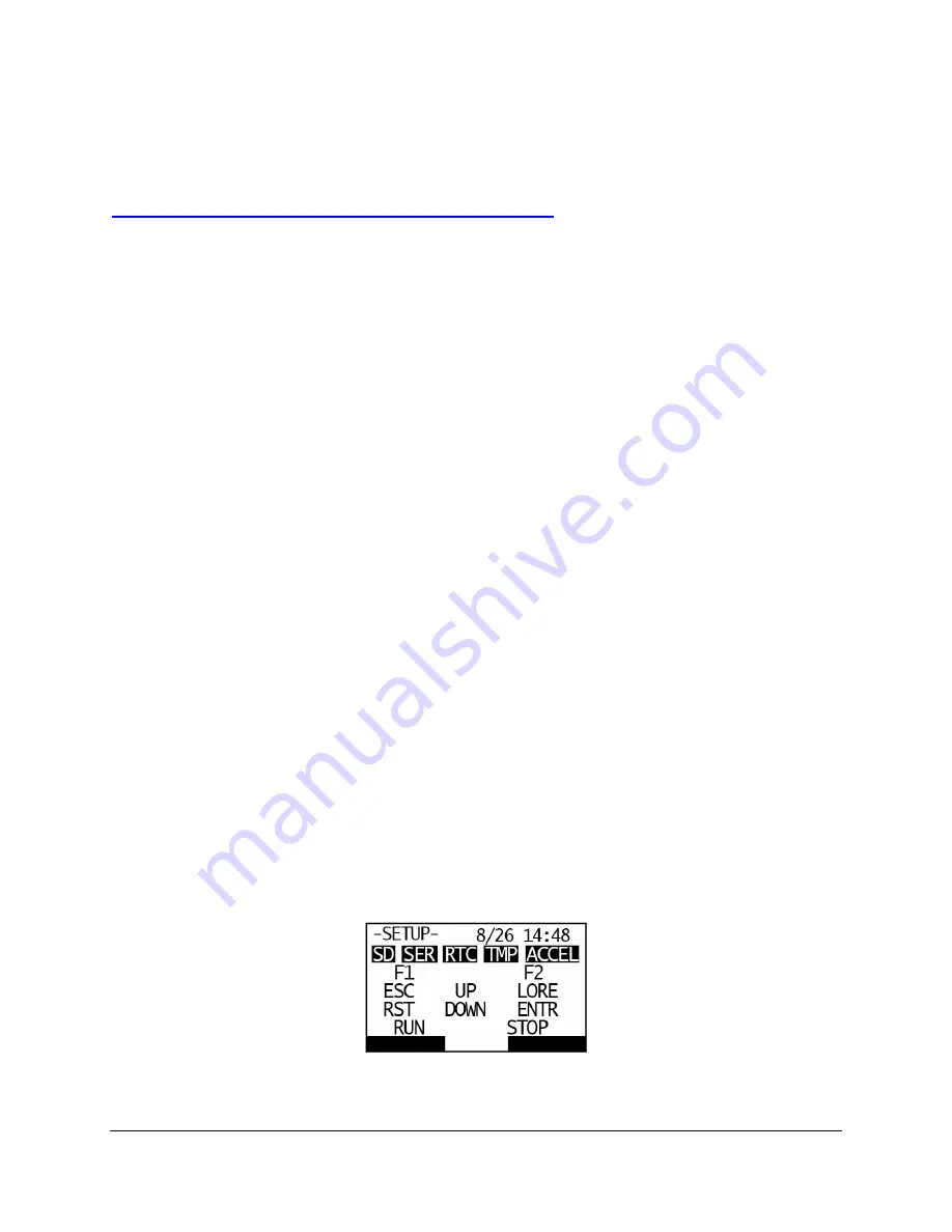
Next, there are five icons on the top row that correspond to internal components including the Internal 
Memory (SD), Serial RJ45 connection (SER), Real Time Clock (RTC), Temperature Sensor (TMP), and 
Accelerometer (ACCEL).  All five of these icons will be shaded as dark boxes if they test out as 
functioning properly.  If any of these boxes are not dark, it may indicate a failed or malfunctioning 
component.   
 
The icons in the lower four rows (F1, ESC, etc.) correspond to their respective keypad keys.  Pressing 
any individual key will convert its icon to a dark box, which indicates that particular key is functioning 
correctly.  If the ENTER key is pressed, the entire display will become dark.  This is to test if any pixels on 
the display have failed.  To go back, press the ESC key once.  If the ESC key is pressed while on the 
Test Screen, its box will turn dark, and the Test Screen will be exited within three seconds. 


Figure 13: Test Screen 

Summary of Contents for DataLogger 4 Series

Page 1: ...Technical Manual Part Number 144 27097 R1 February 2021 Copyright 2021 Magnetek...

Page 2: ...424 7617 24 7 Service pager United Kingdom Telephone 44 0 1675 437297 E mail mh eurosales magnetek com Germany STAHL CraneSystems GmbH Telephone 49 7940 128 0 E mail mh eurosales magnetek com Website...

Page 3: ...responsibility of the owners users and operators of the Magnetek Products to know understand and follow these requirements It is the responsibility of the employer to make its employees aware of the...

Page 4: ...ons WARNING WARNING indicates a potentially hazardous situation which if not avoided could result in death or serious injury CAUTION CAUTION indicates a potentially hazardous situation which if not av...

Page 5: ...ite Parameters from DLS4 to the Drive 10 6 Connecting to a Drive 10 6 1 Drive Compatibility 10 6 2 IMPULSE G VG Series 4 10 6 3 IMPULSE G VG Series 3 10 6 4 IMPULSE G Mini 11 6 3 OmniPulse DDC Series...

Page 6: ...ta 23 11 DataLogger Settings Menu 24 11 1 Set Date Time 24 11 2 Version Firmware Information 25 11 3 Diagnostics 25 11 4 Set Baud 25 11 5 Test Screen 25 12 Panel Mount Bracket 26 13 Connecting to a PC...

Page 7: ...Series 4 to an IMPULSE G Mini or IMPULSE G VG Series 3 drive The DLS4 stores trending data which can be used by IMPULSE Link 5 to generate charts of various monitors The DataLogger Series 4 kit consi...

Page 8: ...ation A new trend data file is created every hour and is labeled by drive model and time stamp 2 3 Parameter Data Overview When the DataLogger is connected to a drive it will read all parameter data a...

Page 9: ...ts an alarm it identifies which alarms are present on the specific drive These are then compared to the Alarm Filters on the DLS4 and any alarms specified to be filtered will not get logged A logged a...

Page 10: ...omatically overwritten when the DLS4 is unplugged and re plugged into a drive or the drive s power is cycled See the Read Parameter Data section on page 22 for detailed information and instructions 5...

Page 11: ...ection Locations 6 3 OmniPulse DDC Series 2 The OmniPulse DDC Series 2 DC motor control drive contains the DLS4 as its standard keypad There is a micro USB port on the front of the drive that allows e...

Page 12: ...s connected to an IMPULSE G VG Series 4 drive the menu is structured the same as the standard keypad It retains the existing functionality plus four additional DataLogger function menus This also appl...

Page 13: ...es 3 drive the menu structure will remain the same as its normal keypad Navigating to the DataLogger functions is executed by pressing the F2 key when the label above the F2 key shows DLS4 Returning t...

Page 14: ...will be simulated on the display and it will function the same as using the integrated keypad Navigating to the DataLogger functions is executed by pressing the F2 key when the label above the F2 key...

Page 15: ...DataLogger Series 4 Technical Manual February 2021 Page 15 of 28 Figure 5 DataLogger Menu Navigation IMPULSE G Mini...

Page 16: ...ent History Menu The Event History menu contains Run Fault and Alarm History logs Counter of the stored Run Fault and Alarm events Filter settings for Faults and Alarms Option to clear the Run Fault a...

Page 17: ...run command or changes direction Various measurements are logged for the duration of the run The Fault History menu contains information for each stored fault event Various measurements are logged at...

Page 18: ...d Alarm Filters The Fault and Alarm filters allow the user to indicate specific faults or alarms that should not be recorded in the Fault and Alarm History logs Press the Down Arrow key until the Alar...

Page 19: ...t are logged in the trend files Frequency Reference Output Frequency Output Current Control Method Motor Speed Output Voltage DC Bus Voltage Output Horsepower Torque Reference Input Terminal Status Ou...

Page 20: ...ed There may be hundreds of trend files so this step may take a while 9 1 Custom Monitors The Custom Monitors allow the user to indicate specific monitors that should get logged in the Trending data A...

Page 21: ...G VG Series 3 U01 17 Term A3 Level U01 18 Mot SEC Current U01 19 Mot EXC Current U01 20 SFS Output U01 29 Load Weight U01 30 SS Delta Speed U01 41 Actual Fin Temp U01 50 Hook Height IMPULSE G Mini U01...

Page 22: ...ngs when the DataLogger was powered on which the user may elect to write back to the drive This slot cannot be overwritten by the user The user may only Write these parameters to the drive Figure 9 Pa...

Page 23: ...ption by pressing the F1 key A Writing Pars message will appear on the display for around 10 to 20 seconds while the parameters are being written 10 3 Clear Parameter Data The parameter data in slots...

Page 24: ...Settings Menu 11 1 Set Date Time The month day year hour and minute can be adjusted individually in this menu For example to make an adjustment to the day press the DOWN or UP arrow to navigate the D...

Page 25: ...depending on the length of the RJ45 cable used If the cable exceeds 50 feet it is possible the DataLogger will not power up If this is the case adjust the Baud Rate to a lower value 11 5 Test Screen...

Page 26: ...in May 2020 contains a battery that is rechargeable and not replaceable The battery will charge when it is plugged into a powered on VFD or if plugged into a PC via USB This hardware has a firmware ve...

Page 27: ...newest version of the firmware may be manually downloaded from Software Downloads on columbusmckinnon com at https www columbusmckinnon com en us software downloads Follow these steps to update the f...

Page 28: ...DataLogger Series 4 Technical Manual February 2021 Page 28 of 28 DataLogger Series 4 Technical Manual January 2021...

Reviews: