background image

20 

(J)

SR27A-AZ Series, CH22 Series

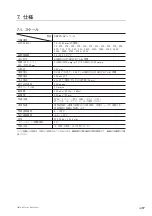
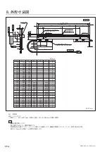
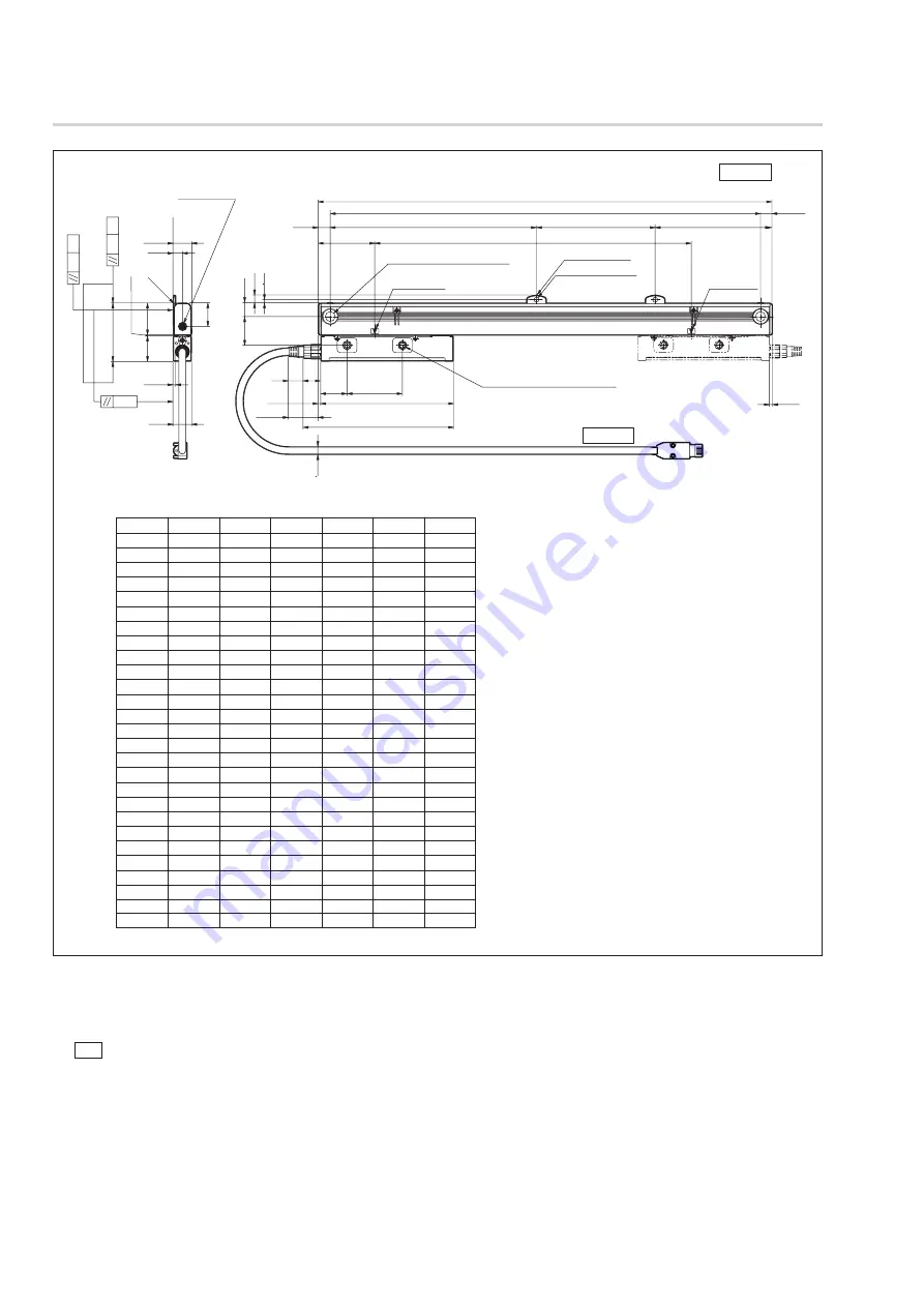
8.  外形寸法図

CH22

6.8

0.1

MG

0.1

MG

0.05

0

±0.2

1

±0.3

31.8

25.1

57.9

23.5

17.6

17.6

8.9

C0.5

L1 = ML + 138

L2 = ML + 115

L3

L4

L5

133

13.5

28.7

56

26

(11.5)

(2.5)

11.5

56.5

151

2.5

(30.5)

ML

15

18

3.5

7.5

エアパージ穴

(M5:両端)

有効長マーク 

有効長マーク 

2-φ10穴 φ15ザグリ深さ9 

 (取付ねじM8 × 16)

2-M6 φ8.0ザグリ深さ5 

 (取付ねじM4 × 20 または M6)

n × φ10穴 

n × 中間フット

*


 (取付ねじM4 × 10)

SR27A

単位: mm

ML

L1

L2

L3

L4

L5

n

70

120
170
220
270
320
370
420
470
520
570
620
670
720
770
820
920

1020
1140
1240
1340
1440
1540
1640
1740
1840
2040

208
258
308
358
408
458
508
558
608
658
708
758
808
858
908
958

1058
1158
1278
1378
1478
1578
1678
1778
1878
1978
2178

   -
   -
   -
   -
   -
   -
   -
   -
   -
   -
   -
   -
392.5
417.5
442.5
467.5
517.5
567.5
627.5
677.5
727.5
520
550
585
620
650
720

   -
   -
   -
   -
   -
   -
   -
   -
   -
   -
   -
   -
392.5
417.5
442.5
467.5
517.5
567.5
627.5
677.5
727.5
515
555
585
615
655
715

0
0
0
0
0
0
0
0
0
0
0
0
1
1
1
1
1
1
1
1
1
2
2
2
2
2
2

   -
   -
   -
   -
   -
   -
   -
   -
   -
   -
   -
   -
   -
   -
   -
   -
   -
   -
   -
   -
   -
520
550
585
620
650
720

185
235
285
335
385
435
485
535
585
635
685
735
785
835
885
935

1035
1135
1255
1355
1455
1555
1655
1755
1855
1955
2155

ML  : 有効長
MG  : マシンガイド

*

中間フット : ML ≧ 670 mm の場合 1 箇所、ML ≧ 1440 mm の場合 2 箇所

注意
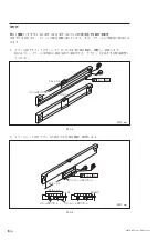
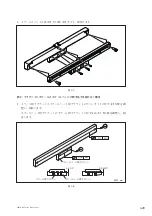
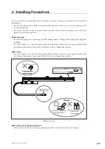
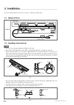
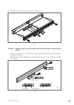
•  ▲面を取付面とします。
•  図に指示するねじは、標準付属品です。
•  有効長 (ML) を超えてスケールヘッドを動かすと破損します。機械の可動長 ( ストローク ) が、有効長 (ML) の両

端から 10 mm 以上内側になる設定を推奨します。

単位 : mm

Summary of Contents for SR27A-AZ Series

Page 1: ...ture references The English version is the original manual according to the EU Machinery Directive Lesen Sie die ganze Anleitung vor dem Betrieb aufmerksam durch und folgen Sie beim Betrieb des Ger ts...

Page 2: ...HE FOLLOWING TWO CONDITIONS 1 T H I S D E V I C E M AY N OT C AU S E H A R M F U L INTERFERENCE AND 2 THIS DEVICE MUST ACCEPT ANY INTERFERENCE RECEIVED INCLUDING INTERFERENCE THAT MAY CAUSE UNDERSIGNE...

Page 3: ...SR27A AZ Series CH22 Series J 1...

Page 4: ...SR27A AZ Series CH22 Series 2 J...

Page 5: ...J i SR27A AZ Series CH22 Series 1 1 1 1 1 1 2 1 1 3 1 1 4 2 1 5 3 1 6 4 2 5 3 6 3 1 6 3 2 6 3 3 11 3 4 12 3 5 13 4 13 4 1 13 4 2 13 5 13 6 14 7 17 7 1 17 7 2 18 7 3 18 7 4 19 8 20 9 21...

Page 6: ...ii J SR27A AZ Series CH22 Series...

Page 7: ...J 1 SR27A AZ Series CH22 Series 1 1 1 SIEMENS DRIVE CLiQ 1 2 SIEMENS DRIVE CLiQ 1 3 SR27A AZ CH22 SIEMENS DRIVE CLiQ 1 1...

Page 8: ...ies CH22 Series 1 4 S R 2 7 A A Z Y SIEMENS DRIVE CLiQ 0 01 m 4 1 A 5 5L 1000 m p p S 3 3L 1000 m p p cm 7 1 C H 2 2 B Y RJ45 Z RJ45 F M12 A M F M12 E M12 S SIEMENS Motion Connect 800Plus C N 010 1 0...

Page 9: ...IEC 60664 1 2007 PWB Printed wiring board EN 61800 5 2 2007 Table D 16 Motion and position feedback sensors IEC 62061 2005 Table D 1 Failure Mode IEC 60068 2 1 IEC 60068 2 2 IEC 60068 2 6 IEC 60068 2...

Page 10: ...4 J SR27A AZ Series CH22 Series 1 6 2006 42 EC...

Page 11: ...J 5 SR27A AZ Series CH22 Series 2 SR27A AZ CH22 S N...

Page 12: ...6 J SR27A AZ Series CH22 Series 3 8 3 1 CH22 SR27A M4 M8 M4 B A M8 3 2 3 2 1 3 1 ML 3 2 3 2...

Page 13: ...J 7 SR27A AZ Series CH22 Series 2 3 M8 16 20 N m M4 10 2 7 N m M4 20 2 7 N m 3 3 3 4...

Page 14: ...8 J SR27A AZ Series CH22 Series 1 1 7 5 0 05 0 1 MG 3 5 2 57 9 0 3 0 0 2 0 05 0 05 MG 57 9 0 3 3 6 mm mm...

Page 15: ...J 9 SR27A AZ Series CH22 Series 3 3 7 2 1 0 1 MG 0 05 MG 0 0 2 0 05 3 8 mm...

Page 16: ...10 J SR27A AZ Series CH22 Series 2 2 0 1 MG 3 9 3 t 1 0 mm t 1 0 mm 3 10 t 1 0 mm 1 mm mm...

Page 17: ...J 11 SR27A AZ Series CH22 Series 3 3 5 mm 1 0 N m 242 1 0 N m 1 3 2...

Page 18: ...DRIVE CLiQ CH22 XXX SFF XXX SEF CH22 XXX SFY XXX SEY 30 CH22 XXX SMF SR27A 30 2 8 7 6 3 4 1 5 2 8 7 6 3 4 1 5 A 3 1 6 2 B SIEMENS DRIVE CLiQ 0V 24V RX N RX P TX P TX N TX P RX P RX N 0V TX N 24V TX N...

Page 19: ...J 13 SR27A AZ Series CH22 Series 3 5 SIEMENS DRIVE CLiQ SINUMERIK 4 4SP2 SINAMICS 4 4SP1 SIEMENS 4 4 1 SIEMENS DRIVE CLiQ 4 1 4 2 3 4 5 SIEMENS DRIVE CLiQ 3 5 DRIVE CLiQ...

Page 20: ...14 J SR27A AZ Series CH22 Series 6 M5 R15 mm 6 4 8 5 m 0 3 m M5 6 6 1 1 5 MPa 1020 kPa 20 kPa 20 200 kPa 5 60 C 5 m 0 3 m 2 Rc PT 1 8 8 1 6 3 150 1020 kPa...

Page 21: ...ries CH22 Series SMC AF40 A 1 SMC AFM40 A 1 SMC AR40 A 200 kPa 1 SMC Y400T A L 2 SMC KQ2S04 M5 1 NC 4 5 m 15 mm 20 10kPa 20 10kPa 6 4 kPa m 0 0 5 10 15 20 25 30 35 40 1 2 3 4 5 6 7 8 9 10 6 2 20 kPa 2...

Page 22: ...16 J SR27A AZ Series CH22 Series 1 30 Nl min 0 0 100 200 300 400 500 600 700 800 900 1000 1 2 3 4 5 6 7 8 9 10 N min PS 6 3...

Page 23: ...670 720 770 820 920 1020 1140 1240 1340 1440 1540 1640 1740 1840 2040 12 1 10 6 C SIEMENS DRIVE CLiQ 20 C ML mm 3 3ML 1000 mp p 5 5ML 1000 mp p 0 01 m DC24 V DC17 30 8 V SIEMENS DRIVE CLiQ 150 mA 2 A...

Page 24: ...ries CH22 Series 7 2 CH22 XXXCS CH22 XXXNS 100 mm PU PU 3 m 5 m 10 m 15 m 1 30 m 0 1 m RJ45 M12 IP67 RJ45 0 50 C 20 55 C 0 1 kg 0 15 kg m 75 mm 40 mm 35 mm 8 7 3 M4 10 2 M4 20 2 M8 16 2 M4 2 t 0 1 mm...

Page 25: ...Fault 22 Wrong Pos detected 21 0 20 0 19 INC Level Fault 18 Other Fault Fault 17 Self Test Fault 16 Mutual Diag Fault 15 0 14 0 13 Service code 1 3 1 3 0 12 F1 11 Service code 1 2 1 2 0 10 Service cod...

Page 26: ...0 1140 1240 1340 1440 1540 1640 1740 1840 2040 208 258 308 358 408 458 508 558 608 658 708 758 808 858 908 958 1058 1158 1278 1378 1478 1578 1678 1778 1878 1978 2178 392 5 417 5 442 5 467 5 517 5 567...

Page 27: ...J 21 SR27A AZ Series CH22 Series 9 3...

Page 28: ...22 J SR27A AZ Series CH22 Series...

Page 29: ...cautions before operating installing maintaining inspecting repairing or otherwise working on this unit Warning indication meanings The following indications are used throughout this manual and their...

Page 30: ...e with other than the indicated power voltage Failure to observe this precaution may result in burns or electric shock Do not install with wet hands Do not perform installation work with wet hands Fai...

Page 31: ...Names of Parts 6 3 2 Installing the Scale Unit 6 3 3 Connection Cable Installation 11 3 4 Wiring Connections with a Controller 12 3 5 Version Numbers of a Controller 13 4 Output Signal 13 4 1 Signal...

Page 32: ...ii E SR27A AZ Series CH22 Series...

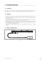
Page 33: ...scale unit and connecting the cable The connection cable is designed to allow connection to either end of the scale head The cable can therefore be routed from the left or right depending on the inst...

Page 34: ...for type C H 2 2 Terminal B specification Y RJ45 connector made by Yamaichi Electronics Z RJ45 connector made by Yamaichi Electronics Water proof F M12 connector male made by Phoenix Contact Terminal...

Page 35: ...of dangerous failure Operating temperature 50 C PFH 41 10 9 1 h Operating temperature 25 C PFH 13 10 9 1 h Operating temperature 0 C PFH 5 10 9 1 h MTTFd 100 years High DCavg 64 01 Low Hardware fault...

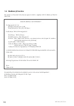
Page 36: ...ools that require high accuracy positioning Serial Number 000001 or later Authorized Representative Magnescale Europe GmbH Antoniusstrasse 14 73249 Wernau Germany Conformity Evaluation Organization T...

Page 37: ...ording Use a clean cloth etc to wipe the surface gently when cleaning it Do not use any organic solvents other than alcohol Even when using alcohol to clean the surface simply wipe it gently CH22 Seri...

Page 38: ...ad holders are removed the approximate positional relationship of the scale and scale head will be maintained However the plastic hook can come off if the scale head is forcibly twisted or other exces...

Page 39: ...etails on the installation method see the later described example installation The foot plates and intermediate foot plate s installed on the scale are used as the installation guides The head holders...

Page 40: ...the scale bracket s parallelism with respect to the machine guide and then secure in place As shown in the figure adjust the parallelism over the entire bracket length even when making a difference in...

Page 41: ...d is not made with the bracket 1 Adjust the parallelism of the scale bracket and scale head bracket with respect to the machine guide and then secure in place Adjust the height and parallelism of the...

Page 42: ...me distance from the right and left scale ends If using a scale with intermediate foot plate be sure to also measure the intermediate foot plate Same distance from scale ends 0 1 MG Fig 3 9 3 Insert t...

Page 43: ...le Water proof cap hexagon socket opposite side 5 mm Use a tightening torque of 1 0 N m for the connector that is used for the connection with the scale head Apply a thread locking agent to the thread...

Page 44: ...N RX P TX P TX N 2 8 7 6 3 4 1 5 TX P RX P RX N 0V TX N 24V A TX N 24V TX P RX P RX N TX P RX P RX N 0V TX N 24V 0V 3 1 6 2 B 30 m 30 m 30 m CH22 XXX SMY SR27A CH22 XXX SFY XXX SEY or Extension conne...

Page 45: ...ler contact SIEMENS 4 Output Signal 4 1 Signal Specification This product performs data communication with the controller using the SIEMENS DRIVE CLiQ protocol Moving the scale head in the direction o...

Page 46: ...4 mm Nylon tube with outer diameter of 8 mm Air pressure source Air filter 5 m filtration Mist separator 0 3 m filtration Pressure reducing valve Distributors Scale unit Air nipple Hex socket head se...

Page 47: ...r of the air supply unit to each scale so that the injection air pressure is uniform for each scale Pressure setting and tube length for pressure reducing valve If the air injection pressure for each...

Page 48: ...urce If a compressor is selected for use take into consideration the air consumption amount approx 30 N min per scale The graph below shows the discharged air amount and rated output as a rough guidel...

Page 49: ...ime is 10 ms Maximum response speed 200 m min Maximum cable length 30 m max Vibration resistance 150 m s2 50 Hz to 3 kHz Impact resistance 350 m sMinion Pro 11 ms Protective design grade IP54 Air purg...

Page 50: ...re range 20 to 55 C Mass Approx 0 1 kg 0 15 kg m Recommended minimum bending radius when there is repeated bending 75 mm Recommended minimum bending radius when there is no repeated bending Conduit un...

Page 51: ...l 0 24 PDV Position data valid 1 invalid 0 23 Hardware Fault Hardware system fault 22 Wrong Pos detected FS position fault 21 Reserved Normally 0 20 Reserved Normally 0 19 INC Level Fault Incremental...

Page 52: ...8 1058 1158 1278 1378 1478 1578 1678 1778 1878 1978 2178 392 5 417 5 442 5 467 5 517 5 567 5 627 5 677 5 727 5 520 550 585 620 650 720 392 5 417 5 442 5 467 5 517 5 567 5 627 5 677 5 727 5 515 555 585...

Page 53: ...and connectors used to connect the unit and controller do not have any problem Check whether the unit has been installed properly check the concentricity and clearances Refer to 3 Installation Proced...

Page 54: ...22 E SR27A AZ Series CH22 Series...

Page 55: ...etriebnahme Installation Wartung Inspektion oder Reparatur dieses Ger tes oder der Durchf hrung anderer Arbeiten durch Bedeutung der Warnhinweise Bei der Durchsicht dieses Handbuchs werden Sie auf die...

Page 56: ...benen Netzspannung Anderenfalls besteht die Gefahr von Feuer und elektrischem Schlag Die Installation nicht mit nassen H nden vornehmen F hren Sie Installationsarbeiten auf keinen Fall mit nassen H nd...

Page 57: ...zeichnung der Teile 6 3 2 Montage der Ma stabseinheit 6 3 3 Installation des Verbindungskabels 11 3 4 Verdrahtung mit einem Steuerger t 12 3 5 Versionsnummern des Steuerger tes 13 4 Ausgangssignal 13...

Page 58: ...ii G SR27A AZ Series CH22 Series...

Page 59: ...Verbindungskabel ist so ausgelegt dass der Anschluss ein beide Enden des Ma stabskopfes m glich ist Das Kabel kann daher je nach dem Installationsort entweder auf der linken oder rechten Seite verleg...

Page 60: ...7 1 f r den Typ C H 2 2 Spezifikation f r Anschluss B Y RJ45 Anschluss von Yamaichi Electronics Z RJ45 Anschluss von Yamaichi Electronics Wasserabweisend F M12 Anschluss Stecker von Phoenix Contact S...

Page 61: ...tions englische version Mode of operation Item High demand continuous mode Probability of dangerous failure Operating temperature 50 C PFH 41 10 9 1 h Operating temperature 25 C PFH 13 10 9 1 h Operat...

Page 62: ...inenrichtlinie Magnescale ist ein sicherheitsorientiertes Produkt das den Vorgaben der Maschinenrichtlinie 2006 42 EG entspricht Der Inhalt der diesbez glichen Konformit tserkl rung ist der englischen...

Page 63: ...ch kann die magnetische Aufzeichnung zerst rt werden Verwenden Sie zum Reinigen ein sauberes Tuch um Staub oder Schmutz sachte abzuwischen Verwenden Sie au er Alkohol keine organischen Losungsmittel B...

Page 64: ...st wenn die Kopfhalter entfernt werden bleibt die ungef hre Positionsbeziehung von Ma stab und Ma stabskopf erhalten Der Plastikhaken kann sich jedoch l sen falls der Ma stabskopf gewaltsam verdreht o...

Page 65: ...nstallationsmethode finden Sie im sp ter beschriebenen Installationsbeispiel Die am Ma stab angebrachten Fu platten und die Zwischenfu platte n werden als Installationsf hrungen verwendet Die Kopfhalt...

Page 66: ...zug auf die Maschinenf hrung berpr fen und einstellen und dann das Teil befestigen Wie in der Abbildung gezeigt ist die Parallelit t ber die gesamte L nge des Halters einzustellen selbst wenn ein Nive...

Page 67: ...dem Halter erzeugt wird 1 Die Parallelit t des Ma stabshalters und des Ma stabskopfhalters in Bezug auf die Maschinenf hrung einstellen und dann die Teile befestigen H he und Parallelit t des Ma stab...

Page 68: ...linken Ende des Ma stabs haben Wenn Sie einen Ma stab mit Zwischenfu platte verwenden messen Sie auch die Zwischenfu platte Gleicher Abstand von den Ma stabsenden 0 1 MG Abb 3 9 3 F hren Sie das mitge...

Page 69: ...chlusselweite des innensechskants von wasserdichter Kappe 5 mm Verwenden Sie f r den Anschluss der Verbindung am Ma stabskopf das Anzugsmoment von 1 0 N m Um zu verhindern dass sich die Verbindung l s...

Page 70: ...3 4 1 5 0 V 24 V RX N RX P TX P TX N 2 8 7 6 3 4 1 5 TX P RX P RX N 0V TX N 24 V A TX N 24 V TX P RX P RX N TX P RX P RX N 0V TX N 24 V 0 V 3 1 6 2 B 30 m 30 m 30 m CH22 XXX SMY SR27A CH22 XXX SFY XXX...

Page 71: ...mit SIEMENS in Verbindung 4 Ausgangssignal 4 1 Signalspezifikationen Die Datenkommunikation dieses Ger tes mit einem Steuerger t erfolgt unter Verwendung eines SIEMENS DRIVE CLiQ Protokolls Wird der M...

Page 72: ...mm Au endurchmesser und 4 mm Innendurchmesser Nylonschlauch mit 8 mm Au endurchmesser Druckluftquelle Luftfilter 5 m Filterfeinheit Tropfenabscheider 0 3 m Filterfeinheit Druckminderungsventil Verteil...

Page 73: ...n mehrere Ma st be einzublasen sollten die Schl uche die gleiche L nge vom Verteiler der Luftversorgungseinheit bis zum jeweiligen Ma stab haben so dass der Einblas Luftdruck f r jeden Ma stab gleich...

Page 74: ...e durchf hren Druckluftquelle Ber cksichtigen Sie bei der Wahl des Kompressors den Luftverbrauch ca 30 N min pro Ma stab Die nachstehende Grafik zeigt die abgegebene Luftmenge und die Nennleistung als...

Page 75: ...nstiegszeit 10 ms betr gt Maximale Ansprechgeschwindigkeit 200 m min Maximale Kabell nge 30 m oder weniger Vibrationsfestigkeit 150 m s2 50 Hz bis 3 kHz Sto festigkeit 350 m s2 11 ms Schutzklasse IP54...

Page 76: ...5 C Masse Ca 10 g 150 g m Empfohlener minimaler Biegeradius bei wiederholtem Biegen 75 mm Empfohlener minimaler Biegeradius ohne wiederholtes Biegen Leitungsrohr Einheit 40 mm keine Leitungsrohr Einhe...

Page 77: ...ltig 23 Hardware Fault Fehler in elektrischen Schaltungen 22 Wrong Pos detected berm ig gro er Fehler in der Positionsinformation 21 Reserviert Normal 0 20 Reserviert Normal 0 19 INC Level Fault Fehle...

Page 78: ...1278 1378 1478 1578 1678 1778 1878 1978 2178 392 5 417 5 442 5 467 5 517 5 567 5 627 5 677 5 727 5 520 550 585 620 650 720 392 5 417 5 442 5 467 5 517 5 567 5 627 5 677 5 727 5 515 555 585 615 655 71...

Page 79: ...des Ger tes an das Steuerger t verwendeten Kabeln und Steckverbindern vorliegt Pr fen Sie nach dass das Ger t einwandfrei installiert wurde berpr fen Sie Rundlaufabweichung und Abstand Siehe Abschnit...

Page 80: ...22 G SR27A AZ Series CH22 Series...

Page 81: ...ent l usage des acqu reurs de l quipement d crit dans ce manuel Magnescale Co Ltd interdit formellement la copie de quelque partie que ce soit de ce manuel ou son emploi pour tout autre but que des op...

Page 82: ......

Page 83: ...SR27A AZ Series CH22 Series 1...

Page 84: ...gawa Intercity Tower A 18F 2 15 1 Konan Minato ku Tokyo 108 6018 Japan 1 16 16 For foreign customers Note This product or technology may be restricted by the government in your country Please make sur...

Reviews: