


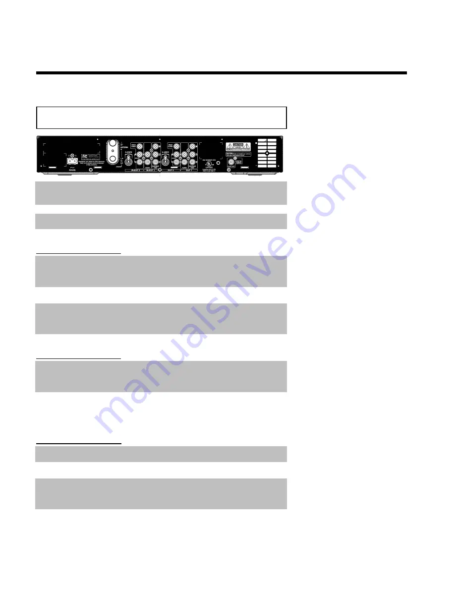
Back ofthe Recorder
4
MAINS
Power plug
: Connection of the power cord here and to the power
outlet (120V/60Hz)
ANTENNA IN
Antenna input
: Connect your antenna or Cable TV signal here
TV OUT
Antenna output
: Connection to the TV with an RF coaxial cable
Input jacks (IN@EXT2)
S-VIDEO (Y/C)
S@Video input
: Connection for an additional device (channel number
'
EXT2
'). Switching between jack
S-VIDEO (Y/C)
and
VIDEO
(CVBS)
is done automatically.
VIDEO (CVBS)
Video input (yellow jack)
: Connection for an additional device
(channel number '
EXT2
')
L AUDIO R
Analog audio input (red/white jacks)
underneath jack
VIDEO
(CVBS)
. Audio for jack
VIDEO (CVBS)
. Connection for an
additional device (channel number '
EXT2
')
Input jacks (IN@EXT1)
AUDIO
Analog audio input (red/white jacks)
next to jack
COMPONENT
VIDEO Y PB PR
: Connection for an additional device. Audio input for
component video (channel number '
EXT1
')
COMPONENT
VIDEO Y PB PR
Component video input (red/blue/green jacks)
: Connection for an
additional device with component video outputs (channel number
'
EXT1
')
Output jacks (OUT@2)
S-VIDEO (Y/C) OUT
S@Video output
: Connection for an S-video-compatible TV
VIDEO (CVBS)
OUT
Video output (yellow jack)
: Connection to a TV with video input
(CVBS, Composite Video)
L AUDIO R OUT
Analog audio output (red/white jacks)
underneath jack
VIDEO
(CVBS)
. Audio for jack
VIDEO (CVBS) OUT
. Connection for an
additional device
Summary of Contents for MRV640
Page 1: ......
Page 12: ......
Page 94: ...82 Notes...
Page 189: ......
Page 190: ...W w n n N w W n N n n w N n W N w w n N w w n N N N W n w n 3139 246 13793 4115 000 MRV640 17...