background image

U

SING THE

CVI (C

OMPONENT

V

IDEO

I

NPUT

) J

ACKS

C

omponent Video inputs provide for
the highest possible color and picture

resolution in the playback of digital signal
source material, such as with DVD play-
ers. The color difference signals (Pb, Pr)
and the luminance signal (Y) connected
and received separately, which allows for
improved color bandwidth information
(not possible when using composite video
or S-Video connections).

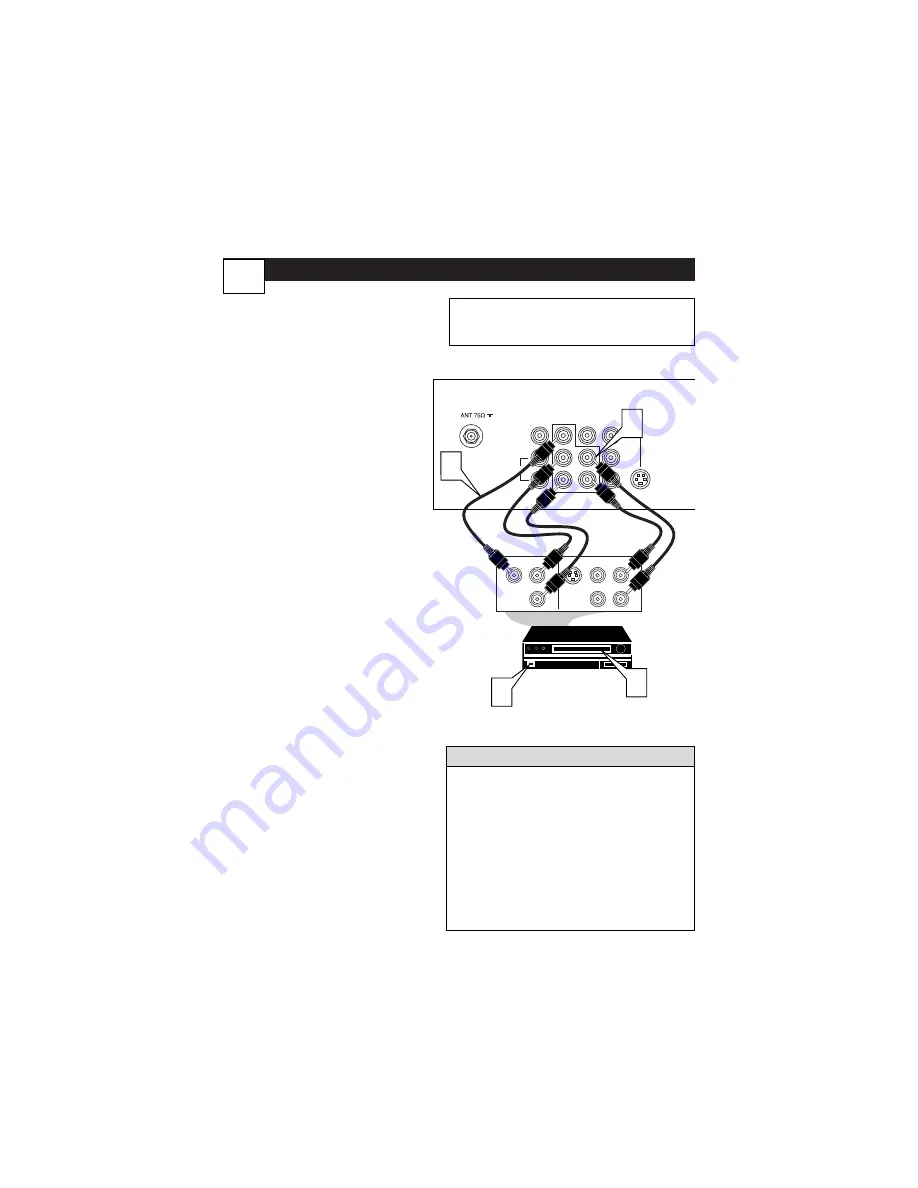
1

Connect the Component (Y,
Pb, Pr) Video  OUT 

jacks from

the DVD player (or similar
device) to the (Y, Pb, Pr) in(put)
jacks on the TV.When using the
Component Video  Inputs, it  is
best not to connect a signal to
the AV

1

IN Video  Jack.

2

Connect the red and white
AUDIO CABLES 

to the Audio

(left and right) output jacks on
the rear of the accessory device
to the Audio (L and R) AV

1

IN

Input Jacks on the TV.

3

Turn the TV and the DVD
(or digital accessory device)
ON.

4

Press the CH + or CH- but-
tons to set the TV to its CVI
channel.

(Go to your lowest

channel, for example channel 1,
then change channels down to find
the correct source channel.)

5

Insert a DVD disc into the DVD
player and 

press the PLAY 

button on the DVD Player.

The description for the component video connec-
tors may differ depending on the DVD player or
accessory digital source equipment used (for exam-
ple,Y, Pb, Pr;Y, B-Y, R-Y;Y, Cr, Cb). Although abbrevi-
ations and terms may vary, the letters 

b

and 

stand

for the blue and red color component signal con-
nectors, and 

Y

indicates the luminance signal. Refer

to your DVD or digital accessory owner’s manual
for definitions and connection details.

Note:

Cables are not supplied with the TV, but are

available from Magnavox or electronics retailers.

H

ELPFUL

H

INT

L/Mono

Monitor out

VIDEO

S-VIDEO

AV1 in

Y

Pb

Pr

AV2 in

AUDIO

R

COMPONENT VIDEO INPUT

S-VIDEO

OUT

OUT

OUT

L

R

AUDIO

VIDEO

COMP VIDEO

Y

Pb

Pr

2

1

3

5

Audio

Cables

(Red and

White)

Component

Video

Cables

(Green, Blue,

Red)

Back of TV

Accessory Device

Equipped with

Component Video

Outputs.

The CVI connection will be dominate over the AV

1

in Video

Input.When a Component Video Device is connected as
described, it is best not to have a video signal connected to
the AV

1

in Video Input jack.

6

Summary of Contents for 27MT5405/17

Page 1: ...T5405 17 Read your Quick Use Guide and or User Manual first for quick tips that make your using your Magnavox product more enjoyable If you have read your instructions and still need assistance you ma...

Page 2: ...tten tion to features for which you should read the enclosed literature closely to pre vent operating and maintenance problems WARNING To reduce the risk of fire or electric shock this apparatus shoul...

Page 3: ...he appliance does not appear to operate normally or exhibits a marked change in performance or E The appliance has been dropped or the enclosure damaged 17 Tilt Stability All televisions must comply w...

Page 4: ...utomatically Program TV 13 Basic Antenna Connection 1 Basic Remote Operation 3 Basic Television Operation 3 Cable Cable Box Basic Connection 1 2 Care and Cleaning 29 Channel Edit 14 Closed Caption Con...

Page 5: ...s threaded screw it down finger tight ANT 75 L Mono Monitor out VIDEO S VIDEO AV1 in Y Pb Pr AV2 in AUDIO R COMPONENT VIDEO INPUT 1 Back of TV Cable signal coming from Cable Company Jack Panel Back of...

Page 6: ...ble box to CH 3 or 4 Tune theTV to the same chan nel and change channels at the cable box Cable Box w Audio Video Outputs This connection will supply Stereo sound 4Connect the Cable Company sup plied...

Page 7: ...ies 2 AA in the remote Be sure the and ends of the batteries line up correctly inside of case is marked 7Reattach the battery lid TELEVISION REMOTE CONTROL BATTERY INSTALLATION Remember the tuned chan...

Page 8: ...cks on the rear of theVCR either one or two or accessory device being used 5Turn theVCR either one or two or accessory device and theTV ON 6Press the CH or CH buttons to set theTV to its AV1or AV2 cha...

Page 9: ...s of the AUDIO red and white CABLES to the AUDIO left and right OUT jacks on the rear of theVCR 3Turn theVCR and theTV ON 4Press the CH or CH buttons to set theTV to its SVHS2 channel Go to your lowes...

Page 10: ...nel 1 then change channels down to find the correct source channel 5Insert a DVD disc into the DVD player and press the PLAY button on the DVD Player The description for the component video connec tor...

Page 11: ...ble to the Monitor out VIDEO plug Connect the other end to theVIDEO IN plug on the secondVCR 4Connect one end of the red and white Audio cable from the Monitor out AUDIO L and R plugs on theTV to the...

Page 12: ...red jack on the SIDE of the television For Mono Devices Connect one end of the audio cable from the Audio Out jack on the device to the Audio L white jack on the SIDE of the television 3Turn the TV a...

Page 13: ...H Button Alternate Channel Press to switch between the last channel and the present channel Details are on panel 27 STATUS EXIT Button Press to see the current channel number Press to remove a menu CC...

Page 14: ...the sound Note Pressing both buttons together will show the onscreen menu MENU Button Press to see the menu Press repeatedly to return to previous menus or remove the menus Arrow 2 3 5 Buttons Press...

Page 15: ...e INSTALL menu features 4Press CURSOR UP or DOWN buttons to scroll the Install features until the word LANGUAGE is high lighted 5Press the CURSOR RIGHT button repeatedly to select ENGLISH FRAN AIS Fre...

Page 16: ...r DOWN buttons to scroll the Install features until the words TUNER MODE is high lighted 5Press the CURSOR RIGHT button to select either ANTENNA CABLE or AUTO mode 6When finished press the STATUS EXIT...

Page 17: ...Your TV can automatically set itself for local area or Cable TV chan nels This makes it easy for you to select only the TV stations in your area when the CHANNEL or buttons are pressed Note Make sure...

Page 18: ...not been skipped 7Using the CURSOR DOWN button scroll the menu to highlight the word SKIPPED 8Now use the CURSOR RIGHT 3 button to toggle between ON or OFF If ON is selected the channel is skipped whe...

Page 19: ...ns to obtain natural skin tones 6Color Temp Press the CURSOR RIGHT 3 3 or LEFT 2 2 buttons to select NORMAL COOL or WARM picture preferences NOR MAL will keep the whites white COOL will make the white...

Page 20: ...left and right speakers 4AVL AutoVolume Leveler Press the or buttons to turn the control On or Off When On AVL will level out the sound being heard when sudden changes in volume occur during commerci...

Page 21: ...select one of the two options 4 3 Expand 4 3 or Compress 16 9 4 3 Standard format for the TV Expand 4 3 Enlarges the picture to fill out the entire screen area eliminating the letter box effect Compr...

Page 22: ...ns material that parents may find unsuitable for children under the age of 13 MOVIE RATINGS Continued R Restricted This is programming is specifi cally designed for adults Anyone under the age of 17 s...

Page 23: ...y learning how to set a per sonal access code 1Press the MENU button on the remote to show the on screen menu 2Press the CURSOR UP 5 or DOWN buttons until the word FEATURES is highlighted 3Press the C...

Page 24: ...you ve entered your access code and the AutoLock features are displayed on the screen 1Press the CURSOR UP 5or DOWN buttons until the words BLOCK CHANNELS are highlighted 2Press the CURSOR RIGHT 3 but...

Page 25: ...ess the CURSOR RIGHT 3 button to turn the control ON or OFF When ON is selected ALL available channels will be blocked from viewing 3When finished press the STA TUS EXIT button to remove the menu from...

Page 26: ...highlight the words MOVIE RATING 2Press the CURSOR RIGHT 3 button to display the MOVIE RAT ING options G PG PG 13 R NC17 or X 3Press the CURSOR UP 5 or DOWN buttons to highlight any of the Movie Rati...

Page 27: ...Y7 TV PG TV 14 TV MA can be customized to blockV vio lence FV fantasy violence S sexual situa tions L coarse language or D suggestive dialogue 4Press the CURSOR RIGHT 3 button on the remote to turn t...

Page 28: ...ng is disabled UNRATED ALL unrated programs based on the Movie Ratings or Parental TV Guidelines can be blocked if this fea ture is set to ON and the BLOCKING feature is set to OFF NO RATING ALL progr...

Page 29: ...CC Mute CC Off CC1 CC2 CC Off 1 2 3 POWER CH CH VOL VOL STATUS EXIT SLEEP MUTE SMART PICTURE SOUND SURF A CH 4 5 6 7 8 9 0 CC MENU MAGNAVOX 3 1 2 Your TV can be set to automatically turn itself off at...

Page 30: ...picture options for watching sporting events WEAK SIGNAL Preset pic ture options for watching pro grams where the reception is not at its best MULTIMEDIA Preset picture options for use with video gam...

Page 31: ...p between the two channels with the touch of only one button After entering the two channels numbers so that one is the last viewed channel and the other is the current channel follow the step below 1...

Page 32: ...emote control If you re attempting to hook up auxiliary equipment check the audio jack connec tions located on the front of the TV Remote Does NotWork Check the batteries If necessary replace them wit...

Page 33: ...n aging of the picture tube Stock market tickers presented at the bottom of the TV screen Shopping channel logos and pric ing displays bright and shown con stantly or repeatedly in the same loca tion...

Page 34: ...part replacement because of improper installation connec tions to improper voltage supply abuse neglect misuse accident unauthorized repair or other cause not within the con trol of Magnavox A product...

Reviews: