background image

37

R

EGULATORY

Cet équipement a été testé et déclaré conforme auxlimites des appareils numériques de 
class B,aux termes de l’article 15 Des règles de la FCC. Ces limites sont conçues de façon 

à fourir une protection raisonnable contre les interférences nuisibles dans le cadre d’une 
installation résidentielle. CET appareil produit, utilise et peut émettre des hyperfréquences 

qui, si l’appareil n’est pas installé et utilisé selon les consignes données, peuvent causer des 
interférences nuisibles aux communications radio. Cependant, rien ne peut garantir l’absence 
d’interférences dans le cadre d’une installation particulière. Si cet appareil est la cause 

d’interférences nuisibles pour la réception des signaux de radio ou de télévision, ce qui peut 
être décelé en fermant l’équipement, puis en le remettant en fonction, l’utilisateur pourrait 

essayer de corriger la situation en prenant les mesures suivantes:

Toutes modifications n’ayant pas reçu l’approbation des services compétents en matière de 
conformité est susceptible d’interdire à l’utilisateur l’usage du présent équipement.

N’utiliser que des câbles RF blindés avec ame en ferrite pour les connections avec des ordinateurs ou périphériques.

• 

Réorienter ou déplacer l’antenne de réception. 

• 

Augmenter la distance entre l’équipement et le récepteur. 

• 

Brancher l’équipement sur un autre circuit que celui utilisé par le récepteur. 

• 

Demander l’aide du marchand ou d’un technicien chevronné en radio/télévision.

C

OMMISSION

 F

EDERALE


DE


LA

 C

OMMUNICATION

 (FCC D

ECLARATION

)

CET APPAREIL NUMERIQUE DE LA CLASSE B RESPECTE TOUTES LES EXIGENCES DU REGLEMENT SUR LE 
MATERIEL BROUILLEUR DU CANADA.

•                 Vous pouvez vous procurer le câble de blindage RF avec tore magnétique dans les différents magasins de détails 
                  ou au centre de service d’usine Phillips.

•                 Le numéro de pièce du câble de blindage RF avec tore magnétique est 3138 198 71441.
•                 Si votre câble de blindage RF ne possède pas de tore magnétique, vous pouvez l’obtenir auprès du centre de  
                  service d’usine Phillips. Suivez les instructions ci-dessous pour l’installation.

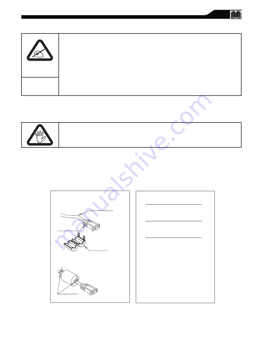
1.   Ouvrez le tore magnétique.
2.   Localisez le connecteur d’écran allant dans l’ordinate ur et 

se branchant dans l’unité. Placez le tore magnétique aussi 
près possible du connecteur d’écran comme illustré dans 

la figure ci-dessous.   

3.   Verrouillez le tore magnétique.


4.   Placez deux attaches à tête d’équerre de câble sur l’un des 

deux côtés du tore ma gnétique pour l’empêcher de glisser 

le long du câble, comme illustré ci-dessous. 

5. Tirez les attaches à tête d’équerre pour enlever le surplus

des broches de raccordement. 


Pour assurer la conformité de cette unité avec 
les limites de la Classe B des règlements de 
la FCC, partie 15, sous-partie B.


Câble d’interface

Connecteur d’écran

Attache de câble


Cet ensemble doit être utilisé lorsque des câbles 

vidéo « sans magnétisme » sont utilisés avec cette unité. 
Cette feuille d’instructions vous donne les détails 

concernant l’installation adéquate. 

Installation du 

tore magnétiqu

Des renseignements FCC additionnels peuvent être 

trouvés dans l’énoncé d’interférence des radiofréquences 
contenus dans le manuel de l’utilisateur.

Tore Magnétique

Summary of Contents for 15MF605T - 15" Lcd Tv

Page 1: ...ONS FIRST TIME SETUP AND ANY OF THE FEATURES WE WANT YOU TO START ENJOYING YOUR NEW PRODUCT RIGHT AWAY CALL US BEFORE YOU CONSIDER RETURNING THE PRODUCT 1 800 705 2000 OR VISIT US ON THE WEB AT WWW US...

Page 2: ...guarantees that your date of purchase will be on le so no additional paperwork will be required from you to obtain warranty service Product Safety Noti cation By registering your product you ll receiv...

Page 3: ...appliance has been dropped or the enclosure damaged Tilt Stability All televisions must comply with recommended international global safety standards for tilt and stability properties of its cabinet...

Page 4: ...nnels 17 Factory Reset 18 Smart Picture and Smart Sound Smart Picture Control 19 Smart Sound Control 19 Picture Menu TV Picture Menu Controls 20 Sound Menu TV Sound Menu Controls 21 Features Menu Auto...

Page 5: ...sheet Unfold the base following the direction as shown on the diagram Place the set upright you LCD TV is now ready for install INSTALLING LCDTV ONTHE WALL The stand of your LCDTV is comply with Stand...

Page 6: ...CH to select channels Point the remote control toward on the front of the LCD TV when operating the LCD TV with the remote Remove the battery compartment lid on the back of the remote Place two AAA b...

Page 7: ...the onscreen menu C C button Press the C C button to select CC on or CC off Standby Power button Press to turn the LCD TV on or off Sleep button Press to set the LCD TV to turn itself off within a cer...

Page 8: ...other end of the adapter to the TV jack on the LCD TV 1 BASIC CABLETV CONNECTION 2 1 Antenna with 75 cable Rear Jack panel of Television Outdoor or Indoor Antenna Combination VHF UHF OR Twin lead wir...

Page 9: ...her end of the cable to the yellow VIDEO jack on the side of the TV Video cables are usually marked with yellow and are available from Magnavox or electronics retailers Video jacks on most equipment a...

Page 10: ...bles usually red and white to the AUDIO OUT left and right jacks on the other equipment Connect the other end of the cables to the AUDIO jack on the side of the LCD TV Plug the DC Adapter into the DC...

Page 11: ...must have an S VIDEO OUT put jack in order for you to complete the connection on this page Connect an S Video cable to the S VIDEO jack of the other equipment DVD Player Camcorder etc and to the S VID...

Page 12: ...ug the DC Adapter into the DC IN 16 V jack on the LCD TV Plug the power cable into an outlet Turn on the LCD TV and other equipment Press the SOURCE button on the remote control to select HD HD will a...

Page 13: ...dio connections are not required the LCD TV can reproduce the computers audio out by an AUDIO ADAPTER to the Audio output jack on the computer if available while connecting the other ends of the Audio...

Page 14: ...u Press the VOL button to select English French or Spanish Press the MENU button repeatedly to clear the menu from the screen 1 2 3 4 5 Remember the LANGUAGE control makes only the TV s onscreen MENU...

Page 15: ...menu Press the VOL or VOL buttons to select CABLE AIR antenna or AUTO Press the MENU button repeatedly to clear the menu from the screen 1 2 3 4 5 6 When CABLE is selected channels 1 125 are available...

Page 16: ...rt the AUTO PROGRAM scanning of channels Press the MENU button repeatedly to clear the menu from the screen after AUTO STORE has nished 1 2 3 4 5 6 After you ve run Auto Program check out the results...

Page 17: ...the INSTALL menu Press the CH button to highlight the CHANNEL EDIT menu Press the VOL button to enter the CHANNEL EDIT menu In CHANNEL column press VOL or VOL to select the channel you wish to add or...

Page 18: ...button repeatedly to clear the menu from the screen 1 2 3 4 5 6 MAIN CONTROLS PICTURE AUDIO FEATURES INSTALL LANGUAGE TUNER MODE AUTO PROGRAM CHANNEL EDIT FACTORY RESET C C SOURCE P I P M E N U OK IN...

Page 19: ...e can be adjusted in picture options within the onscreen menu The Personal mode is the only mode which can be adjusted by the user via the onscreen picture control menu SMART SOUND CONTROL Smart Sound...

Page 20: ...picture become richer in darkness and the white become brighter Sharpness Adjust to improve detail Tint Adjust to obtain natural skin tones TV PICTURE MENU CONTROLS To adjust your LCD TV picture selec...

Page 21: ...anges in volume occur during commercial breaks or channel changes Press the VOL or VOL button to adjust the item Press the CH or CH button to select and adjust other sound controls Press MENU to remov...

Page 22: ...oarse and intensely suggestive language TV RATINGS TV Y All children Appropriate for all children Designed for a very young audience including children ages 2 6 This type of programming is not expecte...

Page 23: ...at 0711 is the default AutoLock code If your access code has been changed by someone other than you a child for example or you have forgotten the code you can always get in by inputting the default co...

Page 24: ...ss the VOL button to block current selected channel or VOL button to unblock a channel Press MENU repeatedly to remove the menu from the screen 1 2 3 4 5 6 7 8 Note You can block additional channels b...

Page 25: ...FF unblocked Press MENU repeatedly to remove the menu from the screen 1 2 3 4 5 6 7 8 9 C C SOURCE P I P M E N U OK MAIN CONTROLS PICTURE AUDIO FEATURES INSTALL SOURCE PICTURE FORMAT AUTOLOCK CLOSED C...

Page 26: ...ocked or OFF unblocked 1 2 3 4 5 6 7 8 9 MAIN CONTROLS PICTURE AUDIO FEATURES INSTALL SOURCE PICTURE FORMAT AUTOLOCK CLOSED CAPTION PICTURE ALIGNMENT C C SOURCE P I P M E N U OK AUTOLOCK LOCK PROGRAM...

Page 27: ...ress VOL button to change the PICTURE FORMAT 1 2 3 4 5 MAIN CONTROLS PICTURE AUDIO FEATURES INSTALL SOURCE PICTURE FORMAT AUTOLOCK CLOSED CAPTION PICTURE ALIGNMENT C C SOURCE P I P M E N U OK 4 3 HD 4...

Page 28: ...2 3 4 5 Note Closed Caption can also be activated by pressing CC button on your remote control Not all TV programs and product commercials are broadcast with Closed Captioning CC Nor are all Closed Ca...

Page 29: ...nual Adjust The Manual Adjust control allow you to manually ne tune the image as it appears on the screen Phase eliminates the horizontal interfering lines Clock eliminates the vertical interfering li...

Page 30: ...t from Stereo Mono and SAP Virtual Sound Adds greater depth and dimension to PC sound AVL Auto Volume Leveler When ON AVL will level out the sound being heard when sudden changes in volume occur durin...

Page 31: ...you would like to adjust SIZE Turn off and set the size of PIP You can choose you preferred size of small medium large or PBP Picture Beside Picture Video Select video source of PIP from AV S Video TV...

Page 32: ...1 640 x 480 VGA VESA 60 59 940 31 469 2 800 x 600 SVGA VESA 56 56 250 35 156 3 SVGA VESA 60 60 317 37 897 4 1024 x 768 XGA VESA 60 60 004 48 363 20MF Series 20 LCD TV No Resolution Mode V Frequency Hz...

Page 33: ...D settings Details are on page 19 or 21 In case you hear wrong sound in S Video or Video CVBS mode Please check if you have connected the right sound signal to AV in S Video or Video input Only one of...

Page 34: ...ng or low contrast graphics are less likely to damage the picture tube Stock market tickers may appear at the bottom of the TV screen if the TV programming covers this news Shopping channel logos pric...

Page 35: ...el Edit 4 17 Closed Captions 4 28 Color 20 F Factory Service 4 38 39 Factory Service Information 38 Factory reset 18 I Index 4 35 L Language 4 14 Limited Warranty 4 39 M Mono 7 21 30 P PC Monitor Conn...

Page 36: ...t expose this appliance to rain or excessive moisture THIS CLASS B DIGITAL APPARATUS MEETS ALL REQUIREMENTS OF THE CANADIAN INTERFERENCE CAUSING EQUIPMENT REGULATIONS RF shield cable with ferrite core...

Page 37: ...N FEDERALE DE LA COMMUNICATION FCC DECLARATION CET APPAREIL NUMERIQUE DE LA CLASSE B RESPECTE TOUTES LES EXIGENCES DU REGLEMENT SUR LE MATERIEL BROUILLEUR DU CANADA Vous pouvez vous procurer le c ble...

Page 38: ...s vente pour les produits apport s ou envoy s par la poste notre centre de service ou le service domicile veuillez contacter Magnavox 1 800 661 6162 Francophone 1 800 705 2000 Anglais ou Espagnol En...

Page 39: ...ted to prerecorded material whether copyrighted or not copyrighted a product used for commercial or institutional purposes WHERE IS SERVICE AVAILABLE Warranty service is available in all countries whe...

Reviews: