background image

25

FCC STATEMENT

This device complies with Part 15 of the FCC rules. Operation is subject to the following two condi-
tions: (1) this device may not cause harmful interference, and (2) this device must accept any interfer-
ence received, including interference that may cause undesired operation.

FCC RADIO FREQUENCY INTERFERENCE WARNINGS & INSTRUCTIONS

This equipment has been tested and found to comply with the limits for a class B digital device, 

pursuant to part 15 of the FCC Rules. These limits are designed to provide reasonable protection 
against harmful interference in a residential installation. This device uses and can radiate radio fre-
quency energy, and if not installed and used in accordance with the included instructions, may cause 
harmful interference to radio communications. However, there is no guarantee that interference will 
not occur in a particular installation. If this device does cause harmful interference to radio or television 
reception, which can be determined by turning the device off and on, the user is encouraged to try to 
correct the interference by one or more of the following methods:
•  Reorient or relocate that device.
•  Increase the separation between the device and the receiver.
•  Connect the device to an electrical outlet on a circuit different from the one connected to the radio 

receiver.

•  Consult the dealer or an experienced radio/TV technician for help.
Please note that the changes or modifications of this product that are not expressly approved by 

the party responsible for compliance could void the user’s authority to operate the equipment.

Summary of Contents for SIDEWINDER

Page 1: ...User Manual SIDEWINDER US SKU RSS160 UPC 810008261538 ...

Page 2: ...n this document and or as a result of the improper unsafe insufficient and negligent assembly installation rigging and operation of this product DOCUMENT VERSION Duetoadditionalproductfeaturesand orenhancements anupdatedversionof thisdocument may be available online Please check www elationlighting com for the latest revision update of this manual before beginning installation and or programming M...

Page 3: ...eturns USA Only 6 Safety Guidelines 7 Overview 9 Operation 10 Control Panel 11 System Menu 12 DMX Channel Functions Values 16 Macro Table 17 Dimensional Drawings 18 Trouble Shooting Cleaning Maintenance 19 Specifications 20 MagFly Module 21 MagRF Module 23 FCC Statement 25 ...

Page 4: ...h Please recycle whenever possible BOX CONTENTS Twist locking power cable x1 CUSTOMER SUPPORT Contact MAGMATIC customer service for any product related service and support needs Also visit forums elationlighting com with questions comments or suggestions ELATION SERVICE USA Monday Friday 8 00am to 4 30pm PST 323 582 3322 Fax 323 832 9142 sales magmaticeffects com ELATION SERVICE EUROPE Monday Frid...

Page 5: ...er manual D This is not a service contract and this warranty does not include any maintenance cleaning or peri odic check up During the periods as specified above Magmatic Effects will replace defective parts at its expense and will absorb all expenses for warranty service and repair labor by reason of defects in material or workmanship The sole responsibility of Magmatic Effects under this warran...

Page 6: ...t pre paid and insured to MAGMATIC in Los Angeles CA or a MAGMATIC Authorized Service Center The RMA number must be clearly written on the outside of the return box and a brief description of the problem and the RMA number must be documented and included in the box Products returned for warranty service without an RMA number clearly marked on the outside of the package will be refused and returned...

Page 7: ...LASS 1 FIXTURE MUST BE PROPERLY GROUNDED THERE ARE NO USER SERVICEABLE PARTS INSIDE THIS UNIT DO NOT ATTEMPT ANY REPAIRS YOURSELF DOING SO WILL VOID YOUR MANUFACTURER S WARRANTY DAMAGES RESULTING FROM MODIFICATIONS TO THIS DEVICE AND OR THE DISREGARD OF SAFETY INSTRUCTIONS AND GUIDELINES IN THIS MANUAL VOID THE MANUFACTURER S WARRANTY AND ARE NOT SUBJECT TO ANY WARRANTY DO NOT PLUG THIS UNIT INTO ...

Page 8: ...y from flames and flammable or explosive substances Never pour flammable liquids such as gas perfume etc into the fog machine Keep the device and fog fluid out of reach of children Use only under adult supervision Do not direct fog output in the direction of people or open flame Stay at least 20 inches 50cm from the output nozzle on the front of the unit Do not obstruct the output nozzle Do not op...

Page 9: ...DMX In 4 DMX Out 5 Wired Remote Port 6 Touch Display Screen 7 Safety Cable Attachment 8 Carry Handles x2 9 LED Array 10 Fog Outlet 11 Mounting Clamp Points x4 12 Tank Level Gauge 13 Latch Screw 14 Tank Access Panel OVERVIEW 9 ...

Page 10: ...randed fluid as doing so can result in severe damage to your device When placing the tank back behind the access panel be careful not to pinch twist or tangle the feed tube connected to the tank cap To close and secure the tank access panel tighten the latch screw by pushing it down while rotating After re connecting the device to a power source and switching it on allow the fluid to warm up for a...

Page 11: ... the fixture s main menu will be displayed see Main Menu Screen below Press the main menu icon you would like to access Use the ENTER button to access sub menus and use the UP and DOWN buttons to make adjustments PresstheENTERbutton to confirmyouradjust ments You may exit the main menu at any time without making any adjustments by pressing the BACK EXIT button CONTROL PANEL 11 ...

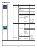
Page 12: ...App DMX Magfly On Off Allows APP data to be converted to DMX data and then sent out via DMX port and Magfly LCD Set Screen OFF Never 10s 40s 1 min 2 min 5 min 10 min 20 min Display Flip 0 deg 180 deg Magfly Set Magfly Channel 0 14 When Magfly is not equipped selecting this function causes Optional Mod ule Not Installed to show on the screen Magfly ON OFF CONTINUED ON NEXT PAGE ...

Page 13: ...e Not Installed to show on the screen Last State Yes No When powered up device adheres to last settings used before power was shut off Default Yes No Restore to factory settings MANUAL LED Off Auto 1 4 Color 1 50 Intensity 0 100 TIMER Interval 0 2500 s Start or pause device operation according to these values by pressure the Play Stop icon Duration 0 250 s LED Off Auto 1 4 Color 1 50 Intensity 0 1...

Page 14: ...s Auto 1 4 Color 1 50 MagRF1 Style LED Off Wireless Remote Button A Auto 1 4 Color 1 50 MagRF2 Style LED Off Wireless Remote Button B Auto 1 4 Color 1 50 MagRF3 Style LED Off Wireless Remote Button C Auto 1 4 Color 1 50 MagRF4 Style LED Off Wireless Remote Button D Auto 1 4 Color 1 50 INFORMATION State Normal Error Slot 1 Null MagFly MagApp MagRF Slot 2 Null MagFly MagApp MagRF CONTINUED ON NEXT P...

Page 15: ...ether MagRemote control is connected MagApp Connect Null No available MagApp source Phone Mobile phone MagApp source Route Router MagApp source No MagApp module not installed MagApp IP Display shows No if MagApp module is not installed MagFly CH 0 14 DMX Addr 1 512 DMX Mode 1 4 7 Timer Int 0s 2500s Timer Dur 0s 250s Heating 0 100 Heater State Normal Error No Heat LCD Ver Vx x Sftwr Ver Vx x ...

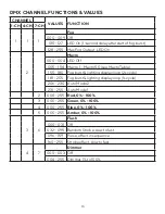
Page 16: ...ro 50 see Macro Table 155 180 Fog burst lighting display loop 2s cycle 181 205 Fog burst lighting display loop 1s cycle 206 230 Auto Mode 2 231 255 Auto Mode 1 2 000 255 Red 0 100 3 000 255 Green 0 100 4 000 255 Blue 0 100 5 000 255 Amber 0 100 3 6 Flash 000 031 Off 032 095 Random Strobe slow to fast 096 159 Pulse effect in sequence 160 255 Strobe effect slow to fast 4 7 Dimmer 000 003 Off 004 255...

Page 17: ... 100 8 026 028 33 101 103 9 029 031 34 104 106 10 032 034 35 107 109 11 035 037 36 110 112 12 038 040 37 113 115 13 041 043 38 116 118 14 044 046 39 119 121 15 047 049 40 122 124 16 050 052 41 125 127 17 053 055 42 128 130 18 056 058 43 131 133 19 059 061 44 134 136 20 062 064 45 137 139 21 065 067 46 140 142 22 068 070 47 143 145 23 071 073 48 146 148 24 074 076 49 149 151 25 077 079 50 152 154 ...

Page 18: ...DIMENSIONAL DRAWINGS Dimensions may not be drawn to scale 18 ...

Page 19: ...ectly the unit will require service Please contact Magmatic Effects for assistance CLEANING MAINTENANCE When storing your device be sure to store in a cool area Cover the device so that dust does not build up on the device When storing for long periods of time it is highly advisable to run the device at least once every 3 4 months Long periods of inactivity can severely shorten the life of your de...

Page 20: ...Light Weight Mobile Design CONTROL 3 DMX Channel Modes 1 4 7 Onboard LCD Touch Control Panel DMX 512 and RDM Protocol Support Optional MagFLY Wireless DMX Transceiver Optional MagRF and Wired Remotes CONNECTIONS 5 pin locking XLR In Out Data Connectors IP65 Locking Input Power Connector With Wired Digital Communication Network SIZE WEIGHT Length 16 26 in 413mm Width 7 60 in 193mm Height 14 80 in 3...

Page 21: ...eiver Wireless DMX Function Without Antenna Dimensions LxWxH 3 1 x 2 2 x 0 8 80mm x 56mm x 21mm Weight 3 2 oz 90g With Long Antenna Dimensions LxWxH 6 7 x 2 2 x 0 8 169mm x 56mm x 21mm Weight 3 5 oz 98g With Short Antenna Dimensions LxWxH 3 6 x 2 2 x 0 8 91mm x 56mm x 21mm Weight 3 3 oz 93g 21 SHORT ANTENNA INSTALLED LONG ANTENNA INSTALLED ...

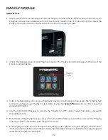
Page 22: ...Magmatic device s touch screen then select the MagFly Set option to configure your MagFly module Refer to your the System Menu section of this manual for detailed information 4 Use the UP and DOWN keys to scroll to the MagFly On Off option Select this option and switch this setting to ON 5 Return to the MagFly Set menu and use the UP and DOWN keys to scroll to and select the MagFly Channel option ...

Page 23: ... with clear line of sight from transmitter to receiver Function varies with Magmatic fixture model 27A 12V Transmitter Battery Receiver Dimensions LxWxH 3 4 x 2 2 x 0 8 86mm x 56mm x 21mm Receiver Weight 1 1 oz 32g Transmitter Dimensions LxWxH 2 6 x 1 4 x 0 6 65mm x 36mm x 15mm Transmitter Weight 1 3 oz 36g 23 ...

Page 24: ...ur Magmatic device s touch screen then select the MagRF Learn option Press any of the four keys on the transmitter to pair the transmitter If pairing is successful a notification reading Connected will appear On the other hand if no action is taken within 20 sec onds or if pairing is unsuccessful a prompt reading Connection Failed will appear 4 After the receiver and transmitter are paired the tra...

Page 25: ...accordance with the included instructions may cause harmful interference to radio communications However there is no guarantee that interference will not occur in a particular installation If this device does cause harmful interference to radio or television reception which can be determined by turning the device off and on the user is encouraged to try to correct the interference by one or more o...

Page 26: ......

Reviews: