Magma MDR 24/96 Quick Start Manual Download Page 2

2

MDR 24/96

MDR 

24/

96

1. Read instuctions — Read, understand and follow all safety and operating

instructions before using the MDR24/96. 

2. Retain Instructions — Keep these safety and operating instructions for future

reference.

3. Heed Warnings — Follow all warnings on the MDR24/96 and in these

operating instructions.

4. Water and Moisture — Do not use the MDR24/96 near water – for

example, near a bathtub, kitchen sink, garden hose, incontinent poodle,
sweaty drummer, etc. – or when condensation has formed on the unit.

5. Heat and Ventilation — Locate the MDR24/96 away from heat sources such

as radiators, campfires, compost pits, heliarc welders, magma flows, etc. Do
not block MDR24/96 ventilation openings or install in spaces that prevent
adequate air circulation to the unit.

6. Power Sources — Connect the MDR24/96 only to a power source of the type

described in these operating instructions or as marked on the MDR24/96.

7. Power Cord Protection — Route power supply cords so that they are not likely

to be walked upon, tripped over, or abraded by items placed upon or against
them. Pay particular attention to cords at plugs, convenience receptacles, and
the point where they exit the MDR24/96.

8. Object and Liquid Entry — Do not drop objects or spill liquids into the

MDR24/96. Clean only with a damp cloth; do not clean with liquid or aerosol
cleaners.

9. Attachments — Use the MDR24/96 with only the accessories specified in

this manual.

10. Damage Requiring Service — The MDR24/96 should be serviced only by

qualified service personnel when:

A. The power supply cord or the plug has been damaged; or

B. Objects have fallen onto, or liquid has spilled into the unit; or

C. The unit has been exposed to rain or water; or

D. The unit does not appear to operate normally or exhibits a marked

    change in performance; or

E. The unit has been dropped, or its chassis damaged.

11. Servicing — Do not attempt to service the MDR24/96. All servicing

should be referred to the Mackie Service Department.

12. Lightning — Unplug the MDR 24/96 during lightning storms or when

unused for long periods of time.

13. Grounding and Polarization — To prevent electric shock, do not use the

MDR24/96 polarized plug with an extension cord, receptacle or other
outlet unless the blades can be fully inserted to prevent blade exposure.
Do not defeat the MDR24/96 grounding by plugging into an ungrounded
receptacle or ground lift adapter.

This apparatus does not exceed the Class A/Class B (whichever is applicable)
limits for radio noise emissions from digital apparatus as set out in the radio
interference regulations of the Canadian Department of Communications.

ATTENTION — Le présent appareil numérique n’émet pas de bruits
radioélectriques dépassant las limites applicables aux appareils numériques de
class A/de class B (selon le cas) prescrites dans le réglement sur le brouillage
radioélectrique édicté par les ministere des communications du Canada.

This product has been tested and complies with the
following standards and directives as set forth by the
European Union:

* EN 55022 Radiated and Conducted Emissions

* EN 61000-4-2 Electrostatic Discharge Immunity

* EN 61000-4-3 RF Electromagnetic Fields Immunity

* EN 61000-4-4 Electrical Fast Transient/Burst Immunity

* EN 60950/IEC 950 Electrical Safety Requirements

FCC Information

NOTE:

 This equipment has been tested and found to comply

with the limits for a Class A digital devices, pursuant to Part 15
of  the  FCC  Rules.  These  limits  are  designed  to  provide
reasonable  protection  against  harmful  interference  when  the
equipment  is  operated  in  a  commercial  installation.  This
equipment  generates,  uses,  and  can  radiate  radio  frequency
energy  and,  if  not  installed  and  used  in  accordance  with  the
instruction  manual,  may  cause  harmful  interference  to  radio
communications. Operation of this equipment in a residential
area is likely to cause harmful interference in which case the
user  will  be  required  to  correct  the  interference  at  his  own
expense.

CAUTION    

AVIS

RISK OF ELECTRIC 

SHOCK 

DO NOT OPEN

RISQUE DE CHOC ELECTRIQUE

NE PAS OUVRIR

CAUTION: TO REDUCE THE RISK OF ELECTRIC SHOCK

DO NOT REMOVE COVER (OR BACK)

NO USER-SERVICEABLE PARTS INSIDE

REFER SERVICING TO QUALIFIED PERSONNEL

ATTENTION: POUR EVITER LES RISQUES DE CHOC

ELECTRIQUE, NE PAS ENLEVER LE COUVERCLE.  AUCUN

ENTRETIEN DE PIECES INTERIEURES PAR L’USAGER.  CONFIER

L’ENTRETIEN AU PERSONNEL QUALIFIE.

AVIS: POUR EVITER LES RISQUES D’INCENDIE OU

D’ELECTROCUTION, N’EXPOSEZ PAS CET ARTICLE 

A LA PLUIE OU A L’HUMIDITE

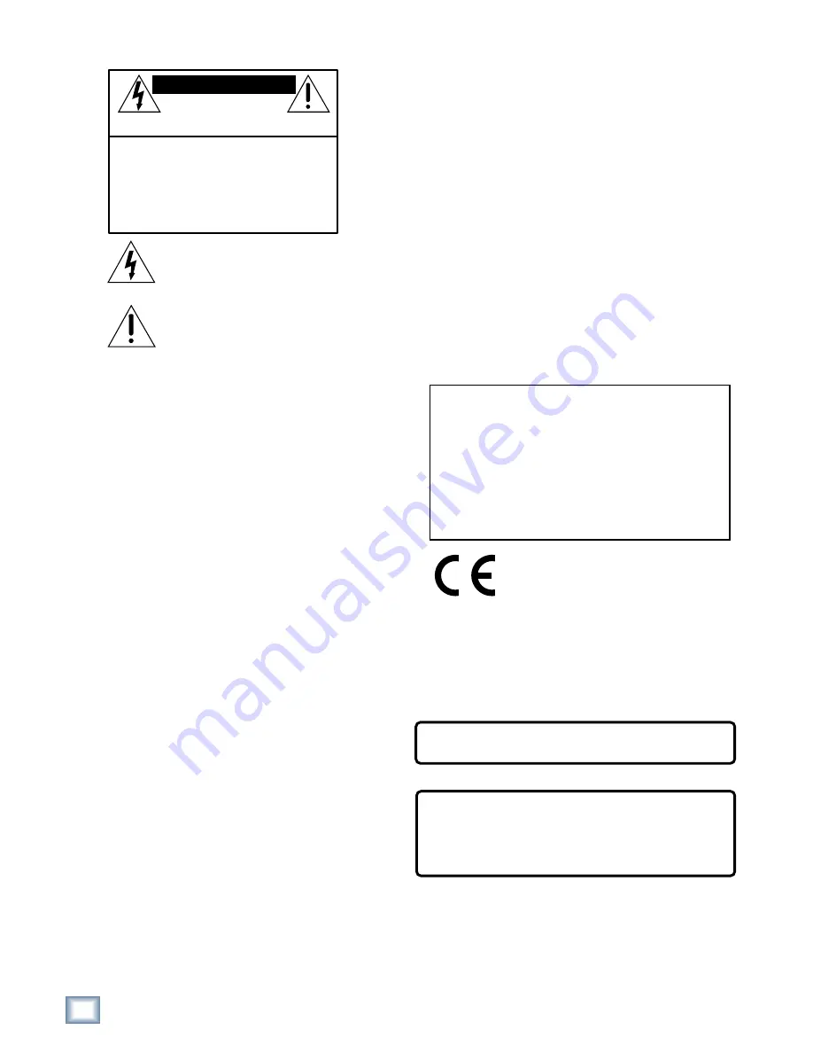
   The lightning flash with arrowhead symbol within an equilateral 
triangle is intended to alert the user to the presence of uninsulated
"dangerous voltage" within the product’s enclosure, that may be 
of sufficient magnitude to constitute a risk of electric shock to persons.

   Le symbole  clair avec point de fl che   l’int rieur d’un triangle 

quilat ral est utilis  pour alerter l’utilisateur de la pr sence   

l’int rieur du coffret de "voltage dangereux" non isol  d’ampleur 
suffisante pour constituer un risque d’ l ctrocution.

   The exclamation point within an equilateral triangle is intended to 
alert the user of the presence of important operating and maintenance 
(servicing) instructions in the literature accompanying the appliance.

   Le point d’exclamation   l’int rieur d’un triangle  quilat ral est 
employ  pour alerter les utilisateurs de la pr sence d’instructions 
importantes pour le fonctionnement et l’entretien (service) dans le 
livret d’instruction accompagnant l’appareil.

Important Safety Instructions

WARNING — Before applying power to the MDR24/96, make sure that the

Voltage Selector switch next to the AC inlet jack on the rear panel is set to
the line voltage used in your region.  Powering-on the MDR24/96 with
the Voltage Selector switch set incorrectly will cause an electrical and fire
hazard that may result in irreparable damage to the unit.

WARNING — To reduce the risk of fire or electric shock, do not expose this

appliance to rain or moisture.

Summary of Contents for MDR 24/96

Page 1: ...24 TRACK 24 BIT DIGITAL AUDIO HARD DISK RECORDER QUICK START GUIDE MDR 24 MDR 24 MDR 24 MDR 24 MDR 24 96...

Page 2: ...e des communications du Canada This product has been tested and complies with the following standards and directives as set forth by the European Union EN 55022 Radiated and Conducted Emissions EN 610...

Page 3: ...ups 18 Analog Hookup AIO 8 18 TDIF Hookup DIO 8 20 ADAT Optical Hookup DIO 8 or OPT 8 22 AES EBU Hookup PDI 8 25 MDR24 96 Operation 27 Opening Projects 27 Time Display 28 Basic Transport Operations 28...

Page 4: ...service please use the shipping box it came in This box has been specially designed to minimize damage to the MDR24 96 during shipping so that it won t end up more broken than when you sent it How To...

Page 5: ...hey do offer some choice tidbits of knowledge that will leave you wiser for the reading This icon identifies information that is critically important to the operation of the MDR24 96 So for your own s...

Page 6: ...act Remote 24 for smaller project studios and the full featured Remote 48 for controlling up to 48 tracks on two MDR24 96 recorders REWIND FAST FWD PLAY STOP RECORD SELECT SELECT SELECT SELECT ON POWE...

Page 7: ...section describes how to install the I O cards and how to connect the MDR24 96 to your console Before you begin you should choose a location for your MDR24 96 considering the following If you re not...

Page 8: ...The OPT 8 is a low cost ADAT Optical only version of the DIO 8 card The previous ADAT information also applies to this card PDI 8 Each PDI 8 carries four stereo pairs eight channels of digital input...

Page 9: ...the MDR24 96 into the bag 5 Hold the new card so the component side faces left and line up the top and bottom edges with the white card guides Push the card all the way into the slot until its facepla...

Page 10: ...us clocks Whenever time code positional synchronization is used all the devices in a system both analog and digital must be synchronized to a common timing speed reference This is often achieved by di...

Page 11: ...e receiving device s With the MDR24 96 configured as a slave connect the word clock out of the master ADAT Optical device to Word Clock In on the MDR24 96 AES EBU PDI 8 With the MDR24 96 as a master s...

Page 12: ...all know hard drives involve some pretty intricate technology So don t shake the little darlin and if a tray has just come in from a freezing car or airplane cargo hold do not install it until it has...

Page 13: ...ote 48 to reset the connection Footswitch Optional For hands free do it yourself punches and other frequently used functions like Play Stop Punch In Out and Take Select connect the cable of a momentar...

Page 14: ...three I O cards 3 Press the Select button corresponding to each DIO 8 card and toggle the selection between ADAT and TDIF 4 Press the Page Left button to return to the previous screen 5 Now select Ou...

Page 15: ...han eight settings you have four one for each pair of channels To set the PDI 8 card options 1 Press Digi I O to enter the Digital I O Card Setup screen 2 Select Rate Convert The Sample Rate Convert s...

Page 16: ...he softest and loudest sounds that can be recorded and captures a more accurate image of the sound Word Clock Divisors 88 2 96 kHz operation only Some devices that support double wide AES at 88 2 and...

Page 17: ...ove to the last page of the Sync Options menu with the Page Right button Select SR 2 In 2 Set the Word Clock Input divisor to On or Off using the Dec Inc or buttons Off selects 1x operation On selects...

Page 18: ...on each of the three snakes to the like numbered Submaster Tape Output jacks on the 8 Bus console This works as long as you don t record more than 8 channels at a time since the Submaster Outputs 9 1...

Page 19: ...Set the Sample Rate and Bit Depth according to your preference It is not necessary to set the D8B and MDR24 96 to the same Sample Rate since with analog connections the sample clocks on the two units...

Page 20: ...R24 96 Word Clock In To make the MDR24 96 the clock master connect its Word Clock Out to the D8B Word Clock In See Figure 1 MDR24 96 Settings 1 Set the Tape Input format for each DIO 8 card to TDIF an...

Page 21: ...N OUT TDIF ADAT OPTICAL Word Clock In TDIF Cables DB25 DIO 8 Cards Word Clock Out Apogee Clock I O Card TDIF Connection NOT WARNING APOGEE DIGITAL I O SYNC IN OUT TDIF ADAT OPTICAL APOGEE DIGITAL I O...

Page 22: ...aster connect its Word Clock Out to the MDR24 96 Word Clock In To make the MDR24 96 the clock master connect its Word Clock Out to the D8B Word Clock In MDR24 96Settings 1 If you have DIO 8 cards inst...

Page 23: ...cal Out Digital 8 Bus DIO 8 Cards NOT WARNING APOGEE DIGITAL I O SYNC IN OUT TDIF ADAT OPTICAL APOGEE DIGITAL I O SYNC IN OUT TDIF ADAT OPTICAL APOGEE DIGITAL I O SYNC IN OUT TDIF ADAT OPTICAL MDR 24...

Page 24: ...ptical Out ADAT Optical Hookup with OPT 8 APOGEE SYNC APOGEE Word Clock Out Word Clock In Word Clock Out MDR24 96 as Master Word Clock Out D8B as Master Word Clock In Word Clock Out Apogee Clock I O C...

Page 25: ...aster set the Sample Clock to Internal if it is a clock slave set the Sample Clock to Word Clock and depress the 75 termination switch on the Sync card 2 Set the Sample Rate to 44 1 kHz or 48 kHz acco...

Page 26: ...ut Word Clock In Word Clock Out MDR24 96 as Master Word Clock Out D8B as Master Word Clock In Word Clock Out Apogee Clock I O Card NOT WARNING MDR Sync Card Word Clock In Word Clock Out Use one only D...

Page 27: ...Note The front panel display blanks after several minutes of being idle Pressing any button below the display will turn it back on Opening Projects The MDR24 96 organizes audio files and session info...

Page 28: ...know Play also punches out of record and cancels master record standby while leaving the Transport in play To put the Transport into play Press Play Fast Wind Rewind and Fast Forward put the MDR24 96...

Page 29: ...ints can be stored either on the fly or when stopped 1 Press Store The Store light will blink to indicate that the MDR24 96 is ready to save a Locate point 2 Press Loc1 or Loc 2 when the Transport is...

Page 30: ...n Cut cuts a hole in the selected Area and copies the Area to the Clipboard Join performs a Cut and then slides everything that occurs after the End point forward in time to fill the gap left buy the...

Page 31: ...Sample Rate mode determines whether your project will be a 24 track Project at 44 1 or 48 kHz or a 12 track Project at 88 2 or 96 kHz Once a Project is created the Sample Rate mode cannot be changed...

Page 32: ...orded on the track before the punch in and after the punch out During the punch you hear what is presently being recorded Auto Input On is the default mode when you power up the MDR24 96 When Auto Inp...

Page 33: ...wo the resulting distortion is uglier than scraping your fingernails across a chalkboard To get the get the best sound from the MDR24 96 1 Turn All Input on 2 Ask the talent to play or sing as loud as...

Page 34: ...l 8 Bus consoles But beware that semi pro consoles often operate at a nominal output level of 10dBV and will run out of steam before reaching a level that can take advantage of the recorder s full res...

Page 35: ...pizza Punch punches in just like pressing Play Record and punches out like pressing Play When playing hitting the footswitch punches in on all armed tracks When recording hitting the footswitch again...

Page 36: ...and select Undo Redo 2 From the Undo Redo menu select Undo Saving Projects Every time you record new audio the audio data and Project information is automatically saved to disk However if you make oth...

Page 37: ...phic data loss and the possible loss of and clients back up your projects on two media before deleting them from your working drive s There now you know better So don t wait until disaster strikes to...

Page 38: ...files that were recorded in the Project but are no longer used in the Playlist Whenever you Purge Audio the History List is cleared To Purge Audio from your hard drive 1 Press the Project button and t...

Page 39: ...Cables HD44 Series DB25 to specify connector Connector options 4 male 4 female XLR or DB25 Standard lengths 5 10 15 20 25 feet Hosa Technology Inc 6920 Hermosa Circle Buena Park CA 90620 Tel 714 736 9...

Page 40: ...c 135 E Kalamazoo Ave Kalamazoo MI 49007 Tel 800 253 7360 Fax 616 388 9681 http ww procosound com AIO 8 Analog Interface Cables DA 88 XM Series DB25 to 8 male XLR s DA 88 XF Series DB25 to 8 female XL...

Page 41: ...0 25 30 35 40 50 OL 2 4 7 10 15 20 25 30 35 40 50 OL 2 4 7 10 15 20 25 30 35 40 50 OL 2 4 7 10 15 20 25 30 35 40 50 OL 2 4 7 10 15 20 25 30 35 40 50 OL 2 4 7 10 15 20 25 30 35 40 50 OL 2 4 7 10 15 20...

Page 42: ...Mike Rivers with proofreading and final blessing by Jeff Gilbert Proofreading and additional editing by Linn Compton Scott Garside was a pain the whole time Demo Music Credits Ode to Masters Written...

Page 43: ..._______________ __________________________________________________________________________________________________________ _____________________________________________________________________________...

Page 44: ......

Reviews: