Page 10 of 18
508196-01
Issue 2120
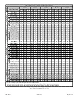
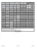
Ventilation Air (CFM) *
Cumulative
Knockouts
Removed
Total External Static Pressure
( return) **
0.1
0.2
0.3
0.4
0.5
0.75, 1.0, 1.5
TON
# 1 Only
7
9
12
15
18
#1 thru #2
10
15
20
24
28
#1 thru #3
12
18
25
32
38
#1 thru #4
18
28
36
45
54
#1 thru #5
23
35
46
57
69
#1 thru #6
27
41
54
67
80
#1 thru #7
32
48
63
78
93
#1 thru #8
37
55
73
90
107
#1 thru #9
41
61
80
100
118
2.0, 2.5, 3.0
TON
# 1 Only
21
20
19
17
16
#1 thru #2
28
27
25
24
22
#1 thru #3
35
33
32
30
28
#1 thru #4
45
42
40
38
35
#1 thru #5
55
52
49
46
43
#1 thru #6
66
62
59
55
52
#1 thru #7
79
75
71
66
62
#1 thru #8
91
86
81
76
71
#1 thru #9
105
99
94
88
82
* Assumes proper speed tap adjustments to maintain nominal supply air CFM
** Assumes equal supply and return static pressures
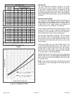
Table 6.
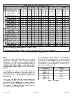
Ventilation
Air (CFM
)
Cumulative Knockouts Removed
0
10
20
30
40
50
60
70
80
90
100
110
120
1
2
3
4
5
6
7
8
9
0.75, 1, 1.5 Ton .225'' Supply & .225''
Return, .45'' Total Duct Static
2, 2.5, 3 Ton .225'' Supply & .225''
Return, .45'' Total Duct Static
Figure 9. Ventilation Air CFM
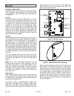
Thermostat
The room thermostat should be located on an inside
wall where it will not be subject to drafts, sun exposure,
or heat from electrical fixtures or appliances. Follow
manufacturer’s instructions enclosed with the thermostat
for general installation procedures. Color-coded insulated
wires (#18 AWG) should be used to connect the thermostat
to the unit.
Electrical Connections
The unit must be electrically grounded in accordance with
local codes or, in the absence of local codes, with the
National Electrical Code ANSI/NFPA No. 70 (latest edition)
or CSA C22.2 Part 1 (latest edition). Any alteration of
internal wiring will void certification and warranty.
Units are factory wired for a 230 volt power supply. If power
supply is 208 volts, it will be necessary to change a wire
connection on unit transformer from 240 volt terminal to
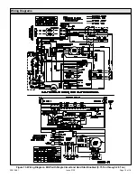
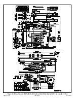
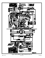
208 volt terminal as shown on the wiring diagram.
Use wiring with a temperature limitation of 75°F minimum.
Run the 208 or 230 volt, single phase, 60 hertz electric
power supply through a fused disconnect switch to the
control box of the unit and connect as shown in the unit’s
wiring diagram.
The power supply to the unit must be NEC Class 1 and
must comply with all applicable codes. A fused disconnect
switch should be field provided for the unit, and must be
separate from all other circuits. If any of the wire supplied
with the unit must be replaced, replacement wire must be
of the type shown on the wiring diagram.
Electrical wiring must be sized to minimum circuit ampacity
(MCA) marked on the unit.
Use copper conductors only
.
Each unit must be wired with a separate branch circuit and
be properly fused.
NOTE:
Some models require two separate power supply
circuits. See the unit wiring diagrams and rating plates for
specifications.


