035-000049-001
Page 18
HCA IOM 1.1 8-28-2017
Refrigerant Piping, Direct-Expansion (DX) Coils
(Cont’d)
EXPANSION VALVE PIPING — Distributor nozzles and
expansion valves sized for acceptable performance for a
range of conditions are factory supplied. Use the AHU (air-
handling unit) selection program in the electronic catalog to
select optimal nozzle sizes.
Circuiting selection should result in a circuit loading of 0.8
to 2.0 tons per circuit at design load. Circuit loading must
be evaluated at minimum load to ensure that it does not
drop below 0.6 tons per circuit. Solenoid valves may be
used, if necessary, to shut off the refrigerant supply to indi-
vidual expansion valves to maintain adequate coil circuit
loading.
Compressor minimum unloading and TXV quantity is nec-
essary to determine minimum tonnage per circuit.
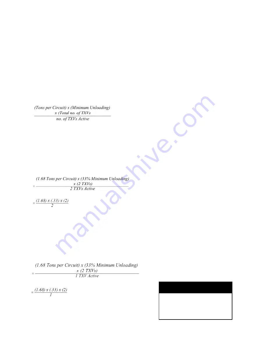
Minimum Unloading Equation:
Example:
Condensing Unit: 38ARS012
Minimum Unloading:
33%
Coil: 6 row, 11 FPI, Half Circuit
Coil Tons per Circuit: 1.68
Total TXVs: 2
In the first example we will determine the tons per circuit
when both TXVs are active and the compressor is unload-
ed to its minimum of 33%
= .55 tons per circuit at minimum unloading UNACCEPTA-
BLE
If we install a liquid line solenoid valve before one of the
TXVs and close it so that only one TXV is active when the
compressor is unloaded to its minimum of 33%, we see the
following:
= 1.10 tons per circuit at minimum unloading ACCEPTABLE
There are three different options to control
tons per circuit when using an unloading
compressor. The first is to use drop solenoid
valve control as illustrated above and let the
suction cutoff unloaders “ride” with the load.
The second is to use drop solenoid valve
control as illustrated above with electric un-
loaders and let the control algorithm deter-
mine the combination of solenoid valves and
unloaders to limit tons per circuit to accepta-
ble limits. The third is to limit the minimum
amount of unloading so that tons per circuit
is within acceptable limits.
TXV SENSING BULB—sensing bulb for
TXV is shipped coiled up inside cabinet.
Remove coil connection panel, route sens-
ing bulb out through suction line hole in pan-
el, reinstall panel. Locate sensing bulb on
horizontal section of suction line , and attach
to tubing using copper plated strap. Attach
sensing bulb between but no lower than the
2-o’clock and 10-o’clock positions. Make
sure that there is good contact between the
bulb cylinder and tubing. INSULATE the
sensing bulb to insure that it reads the tem-
perature of the suction line. For dual-circuit
DX coils, make sure to locate the sensing
bulb on the correct suction line.
Electrical Installation
WARNING
To avoid possible injury or death due to
electrical shock, open the power supply dis-
connect switch and secure it in an open po-
sition during installation.
All field-installed wiring, including the electri-
cal ground, MUST comply with the National
Electrical Code (NEC) as well as applicable
local codes. In addition, all field wiring must
conform to the Class II temperature limita-
tions described in the NEC.
Refer to factory wiring diagrams installed in
the unit.
CAUTION
Use only copper conductors for field
-installed electrical wiring. Unit ter-
minals are not designed to accept
other types of conductors.
Summary of Contents for HCA 04
Page 2: ...035 000049 001 Page 2 HCA IOM 1 1 8 28 2017 THIS PAGE INTENTIONALLY LEFT BLANK...
Page 26: ...035 000049 001 Page 26 HCA IOM 1 1 8 28 2017...
Page 28: ...035 000049 001 Page 28 HCA IOM 1 1 8 28 2017 THIS PAGE INTENTIONALLY LEFT BLANK...
Page 29: ...035 000049 001 Page 29 HCA IOM 1 1 8 28 2017 THIS PAGE INTENTIONALLY LEFT BLANK...


