Document # 5310260-01 Rev-02 (08/22/2012)
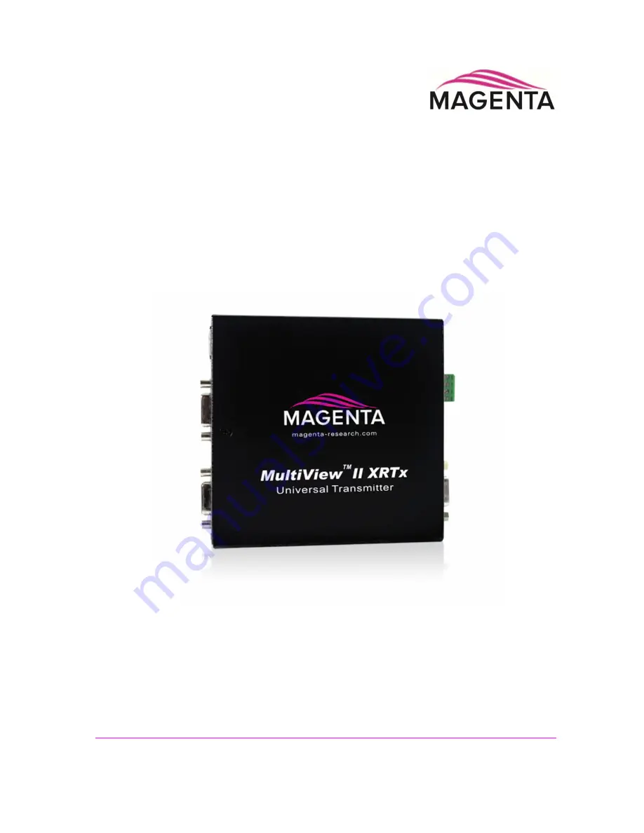
MultiView II
XRTx
Transmitter
Installation and User Guide
TM
Page 1: ...Document 5310260 01 Rev 02 08 22 2012 MultiView II XRTx Transmitter Installation and User Guide TM...
Page 2: ...tware or documentation including their quality performance merchantability or fitness for a particular purpose As a result this software or documentation is licensed as is and you the licensee are ass...
Page 3: ...osure which may present a risk of electric shock damage to equipment or facilities Caution Read instructions Read and understand all operating installation and safety instructions before using this eq...
Page 4: ...Wan Hong Kong Main 852 3105 1493 Fax 852 3105 1491 Contact awaung magentaresearch asia com Sales awaung magentaresearch asia com Pan European Office includes Japan Australia etc Magenta Research LTD...
Page 5: ...iary Signal Support SA Version 7 3 4 4 Auxiliary Signal Support SAP Version 8 3 5 CAT5 Cable Compatibility 8 Chapter 4 Installation 10 4 1 Prerequisites 10 4 2 Installation Procedure 11 4 3 Configurat...
Page 6: ...XRTx A Supports L R summed audio user configuration setting MVII XRTx S Supports simplex serial user configuration setting MVII XRTx 232 Supports 9 wire RS 232 serial simplex or duplex TX RX with hard...
Page 7: ...front panel of the XRTx has the following ports controls and indicators There are two buttons COPY CFG and DDC MODE SEL and several green LED status indicators All are used to display and control the...
Page 8: ...ules Stereo L R audio input 10K ohms input impedance A source device with 600 ohms maximum output impedance is recommended RS 232 input 4 75K ohms input impedance Local output port drive impedance The...
Page 9: ...llowing table describes the specifications of the VGA interface video in and local video out Table 3 VGA Interface Specification Item Description Video Support Video input formats video input port Max...
Page 10: ...if simply using the factory default DDC profile Finally the XRTx supports a pass through mode where the DDC profile of a locally attached display is passed directly to the video source This can be ver...
Page 11: ...he A or S versions to support digital S PDIF audio The option module 232 SA SAP is a factory installed option However a field upgrade to a 232 SA or SAP version is possible It will require some minor...
Page 12: ...talled The AUX I O connector on the XRTx is ignored In applications where an XRTx 232 transmitter is routed through a DA Distribution Amp such as a MultiView 9D for example or a Mondo or other video s...
Page 13: ...nder serial control The SAP module provides many additional user configurable settings available through the serial port Please refer to the SAP II Programmer s Guide for additional details Note that...
Page 14: ...standard CAT6 and may require skew compensation beyond what the standard product offers Please contact Magenta Research for assistance The CAT5 5e 6 cable should be suitably rated Listed cable DUZX co...
Page 15: ...through an Ethernet network Do not connect these devices to any sort of networking or telecommunications equipment Do not connect DC power until instructed to do so 4 1 Prerequisites Depending on the...
Page 16: ...the transmitter LINK OUT port 4 Make your audio or serial connections via the phoenix AUX I O connector or DB9 IOIO serial connector as appropriate for your XRTx transmitter model 5 Connect the DC po...
Page 17: ...alled 2 Connect the CAT5 cable to the LINK IN connector If you are daisy chaining multiple receivers also connect the downstream CAT5 cable to the LINK OUT port on the receiver 3 Apply power to the re...
Page 18: ...on settings the XRTx must be in CONFIG mode CFG indicator is on Once in CONFIG mode any changes are effective immediately and are saved in non volatile memory To enter configuration mode 1 Press CFG b...
Page 19: ...are intended to support the most popular VESA standards in standard or widescreen formats Press the DDC MODE button until the STD indicator LED6 is on LOCAL the DDC profile from a locally connected di...
Page 20: ...Press and release the SEL button once You will now be able to change sync mode settings 3 LED indicators 1 3 should be illuminated either DIM or ON all others indicators 4 8 should be off 4 Press the...
Page 21: ...now be able to change 4th pair option settings 3 LED indicators 4 6 should be illuminated either DIM or ON all others indicators 1 3 7 and 8 should be off 4 Press the CFG button repeatedly to step thr...
Page 22: ...detect AC DC coupling mode based on input signal This is the factory default mode dim ON Video input is DC coupled ON dim Video input is AC coupled no DC restore function ON ON Video input is AC coup...
Page 23: ...elay issue See section on skew adjustments in the applicable receiver manual There may be a DDC compatibility problem Try changing the DDC mode setting or copying the DDC profile directly from the dis...
Page 24: ...e rated cable length of the receiver if using low skew cable When daisy chaining the maximum cable distance is not increased beyond the rated distance of the receiver used For example an AK600 can onl...
Page 25: ...apter plug DB9 Female to Male is used to connect an external serial device for example a PC to the XRTx transmitter The DB9 F serial port is only available on XRTx 232 SA and SAP models Table 16 DB9 F...
Page 26: ...Audio Composite Video SA Audio SAP Audio 1 SIG1 Left Channel Tx Signal Signal Left Channel Left Channel 2 GND Ground ground Signal Signal Ground Ground 3 SIG2 Right Channel Right Channel Right Channe...
Page 27: ...5 5mm ID 2 5mm accepted center pin diameter Length 11mm overall length of insertable plug end Inner contact pin socket 5VDC Outer contact sleeve Ground It is highly recommended that the inner contact...
Page 28: ...568B CAT5 Specification Figure 8 T568B CAT5 Table 18 T568B CAT5 Pins PIN COLOR PAIR 1 White Orange Stripe 2 2 Orange Solid 2 3 White Green Stripe 3 4 Blue Solid 1 5 White Blue Stripe 1 6 Green Solid 3...
Page 29: ...dard HD 15 female connectors three row 15 pin Figure 10 HD 15 Female Connector Table 19 HD 15 Connector Pins Pin RGBHV RGBS RGsB Com SVHS YUV 1 Red Red Red C V 2 Green Green Green C Y Y 3 Blue Blue Bl...
Page 30: ...board Table 20 Transmitter 232 Module Jumper Settings Mode Type Baud Max JP1 1 2 JP1 3 4 1 Simplex one way to 1500 ft 115k OUT IN 2 Full Duplex 2 way Short 500 ft 19 2K OUT OUT 3 5 Default Setting Ful...
Page 31: ...1 2 See Notes 3 4 See Notes 5 6 IN 7 8 IN 9 10 OUT 1 2 IN 3 4 OUT 5 6 OUT 7 8 IN 9 10 OUT 5 Default Full Duplex 2 way Long to 1500 ft 19 2k 1 2 OUT 3 4 OUT 5 6 OUT 7 8 IN 9 10 OUT 1 2 OUT 3 4 IN 5 6 I...
Page 32: ...switches you will need to open the receiver enclosure and set the DIP switches directly on the SAP module The DIP switch has 8 switches one for each address bit position Use the SAP addressing chart...
Page 33: ...1 2 3 4 8 OFF 1 5 ON 1 5 6 ON 1 5 7 ON 1 5 6 7 ON 2 3 4 6 7 8 OFF 2 3 4 7 8 OFF 2 3 4 6 8 OFF 2 3 4 8 OFF 2 5 ON 2 5 6 ON 2 5 7 ON 2 5 6 7 ON 1 3 4 6 7 8 OFF 1 3 4 7 8 OFF 1 3 4 6 8 OFF 1 3 4 8 OFF 1...
Page 34: ...1 5 6 7 8 ON 2 3 4 6 7 OFF 2 3 4 7 OFF 2 3 4 6 OFF 2 3 4 OFF 2 5 8 ON 2 5 6 8 ON 2 5 7 8 ON 2 5 6 7 8 ON 1 3 4 6 7 OFF 1 3 4 7 OFF 1 3 4 6 OFF 1 3 4 OFF 1 2 5 8 ON 1 2 5 6 8 ON 1 2 5 7 8 ON 1 2 5 6 7...
Page 35: ...ion 2211053 01 Rigid mount bracket This mounts a single device to a surface wall desk etc Comes with 4 self tapping screws 8310207 02 1U Rack mount Plate for standard 19 rack Mounts 4 devices in a 1U...
Page 36: ...flow Within a rack assembly cable bundles and other equipment in the same rack can impede proper cooling In some rack mount applications you may even need to leave a 1U gap using a blank filler plate...
Page 37: ...Research as an aid in system design and configuration You may download them from the Magenta website www magenta research com There is no charge for obtaining these drawings Table 23 MultiView II XRTx...
Page 38: ...erique de la classe A est conforme a la norme NMB 003 du Canada EUROPEAN UNION DECLARATION OF CONFORMITY Warning This is a Class A product In a domestic environment this product may cause radio interf...
Page 39: ...procedure 11 Mounting kits 30 Option module settings 232 option module 25 SAP option module 27 Pinouts auxiliary signal port 21 Phoenix connector 21 power connector 22 serial port 20 UTP CAT5 link por...