10
WASP Line Array User Manual rev 1.00
in
fo@mag-audio
.c
om
Tel./F
ax:
+38 044 277
-4
7-89
www
.mag-audio.com
5. System operation
5.1. Rigging
WASP line array comes with built-in mounting hardware for ground stack and flying cluster installation
options.
Rigging must be performed only by trained personnel following the established safety rules.
MAXIMUM WEIGHT RESTRICTIONS MUST BE FOLLOWED AT ALL TIMES!
MAKE SURE THE SUPPORT STRUCTURE IS CAPABLE OF HOLDING THE APPLIED WEIGHT WHILE
SUSPENDING THE SYSTEM!
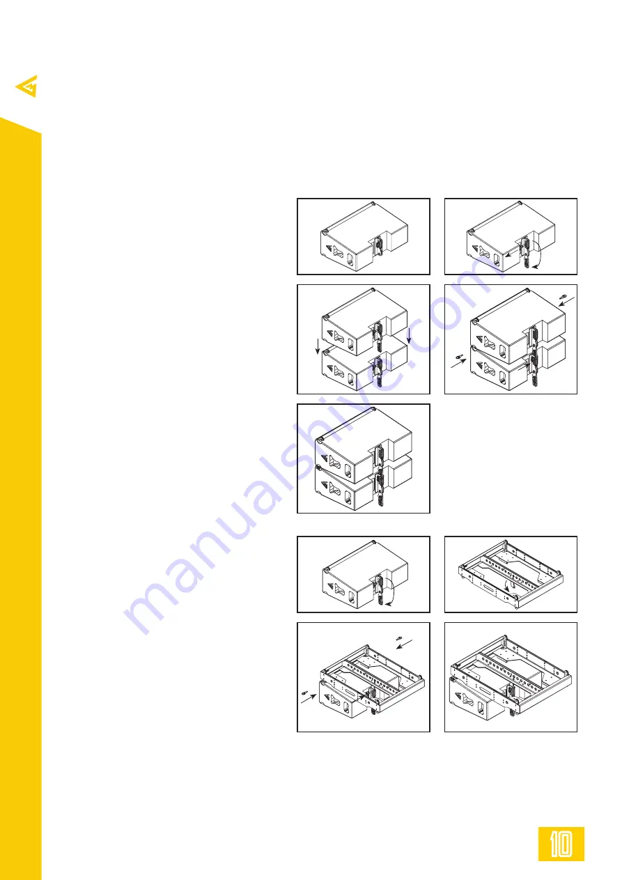
5.2. Connecting two WASP modules
Required accessories:
VA-0010 (part No. 0209000001) - 2 pcs
VA-0018 (part No. 0209000021) - 1 pcs
- Release rear VA-0018 10 mm pin and
drop rear link down on both cabinets
(Pic 1, Pic 2).
- Position two WASP modules on top of
one another, align cabinets’ so their front
links will fit into each other (Pic 3.)
- Insert two VA-0010 8 mm pins into left
and right front links, choose required splay
angle using rear link, and insert one VA-
0018 10 mm pin into corresponding slot of
the rear link.
- Add additional cabinets if needed on top
(for ground stack) or on the bottom (for
flown rack).
5.3. Connecting a flying frame on the top
of a WASP module
Required accessories:
WSF-01 (part No. 108017000) - 1 pcs
VA-0010 (part No. 0209000001) - 2 pcs
VA-0018 (part No. 0209000021) - 1 pcs
- Release rear VA-0018 10 mm pin and
drop rear link down on WASP cabinet
(Pic 1).
- Release link on the WSF-01 flying frame
(Pic 2).
- Place the WSF-01 frame on top of the
WASP cabinet, align so front and rear links
of a cabinet fit into receptacles of the
frame (Pic 3).
- Insert two VA-0010 8 mm pins into
left and right front links of the cabinet,
choose required splay angle using rear link,
and insert one VA-0018 10 mm pin into
corresponding slot of the rear link. (Pic 4).
1
1
3
3
5
2
2
4
4


