background image

1

Chapter   Installing the Display

Installing Your LCD Monitor

Follow the instructions below to set up and install the monitor.


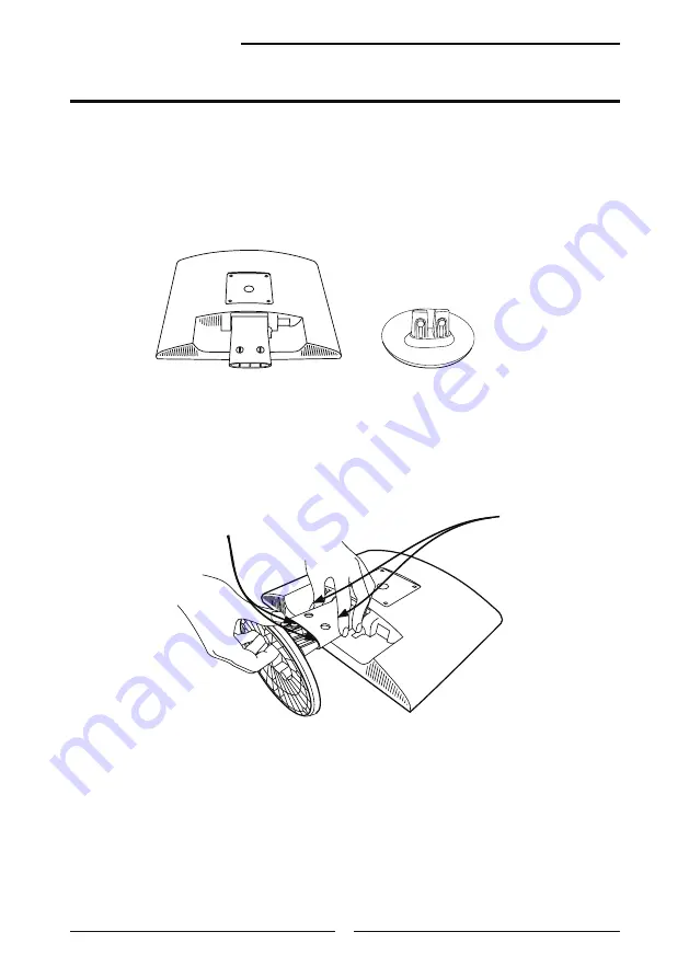
Cover an even stable surface with a soft cloth. Place the unit face-down 

on the cloth. Fit the stand onto the bottom of the display unit as shown, 

then push until the two latches snap into their sockets.


The package contains:


Display unit


Stand

LATCHES

LATCH 

SOCKETS

Summary of Contents for BP919W

Page 1: ...BP919W USER S GUIDE 19 WIDELCDMONITOR ...

Page 2: ...ng without limitation material generated from the software programs which are dis played on the screen such as icons screen displays looks etc All MAG product names mentioned in this publication are trade marks of MAG Other company trademarks are also acknowledged Changes are periodically made to this document Changes technical inaccuracies and typographic errors will be corrected in subsequent ed...

Page 3: ...talling the Display Connecting Your LCD Monitor to a Computer 12 Method 1 Analog D SUB Connection 12 Method 2 Digital DVI Connection 13 Installing Your LCD Monitor 16 Chapter 3 Using the OSD On Screen Display Menu Using the OSD Menu 17 The OSD Options 18 Chapter 4 Technical Information Preset Mode Timing Chart 21 DVI Connector PIN Assignment 22 D SUB Connector PIN Assignment 23 Plug and Play 24 Vi...

Page 4: ...view repair com leo starckx proview repair com ASIA When disposing of MAG Branded Monitors in Asia please contact the following location to make arrangements for recycling Proview Technology ShenZhen Co Ltd North Block 21 23 Shatoukok Free Trade Zone ShenZhen China Mr Dennis Chang Tel 86 755 2526 1512 Fax 86 755 2526 1565 Email recycling proview com cn AMERICA When disposing of MAG Branded Monitor...

Page 5: ...ctive as amended by Directive 93 68 EEC The electro magnetic susceptibility has been chosen at a level that gives correct operation in residential areas business and light industrial premises and small scale enterprises inside as well as outside of the buildings All places of operation are characterized by their connection to the public low voltage power supply system ...

Page 6: ...tallation If this equipment does cause harmful interference to radio or television reception which can be determined by turning the equipment off and on the user is encouraged to try to correct the interference by one or more of the following measures 1 Reorient Relocate the receiving antenna 2 Increase the separation between the equipment and receiver 3 Connect the equipment into an outlet on a c...

Page 7: ...use the equipment and cart stand to overturn Do not disable the 3 wire grounding type plug The grounding pin on the 3 prong plug is an important feature Removing the grounding pin will increase the risk of damaging the equipment If you can not fit the plug into the electrical outlet contact an electrician to install a grounding outlet Always operate this equipment from the type of power source ind...

Page 8: ...ays remove the power cord from the outlet before cleaning the equipment Never use liquid or aerosol cleaners on the equipment Clean only with a soft dry cloth Do not expose the equipment to extreme temperature or to direct sunlight as the equipment may heat up and suffer damage Do not install the equipment near any heat sources such as radiators heat registers stoves or any other apparatus that mi...

Page 9: ...is abnormal DISPOSAL OF WASTE ELECTRONIC EQUIPMENT BY PRIVATE HOUSEHOLDS WITHIN THE EUROPEAN UNION This sign indicates that this product may not be disposed of with your regular household waste The recycling and separate collection of such products is your responsibility Please drop off the above mentioned waste at a designated place for recycling waste electrical and electronic equipment If you d...

Page 10: ...n and set up MULTIMEDIA ENHANCED SPEAKERS True multimedia sound without using valuable desktop space The LCD monitor features two built in 2w stereo speakers integrated into the stylish design INTEGRATED POWER DESIGN The power part is integrated into the whole design and there s no more external power adapter to occupy your desktop space WIDE SCREEN VISION A wide screen offer more space than 4 3 o...

Page 11: ...s product to the original place of purchase Package Contents Power cord specification H05 VV F 3G 0 75mm2 LCD Monitor D SUB Cable Power Cord Warranty Card Quick Guide CD ROM Driver Manual CAUTION Be sure to save original box and all packing material for future transport of monitor Audio Cable BP919W QUICK GUIDE 19 WIDELCDMONITOR Warranty Card ...

Page 12: ...ively Adjusts the speaker volume up and down MENU Press once to display the OSD On Screen Display And press to activate the items you highlight LED The LED light indicates when the LCD monitor is activated blue light indicates power on and amber light indicates power saving Turns the LCD monitor on and off AUTO Press to automatically adjust the display settings to optimize performance based on the...

Page 13: ...n the right side of the main unit to turn the monitor on then turn the computer on If the monitor displays an image the monitor is successfully installed If no image is displayed check all connections Refer to the owner s manual of the computer for connections In the process of connecting external equipment do not connect any AC power cords to wall outlets until all other connections are completed...

Page 14: ...ot disconnect the device from the main voltage To completely disconnect the main voltage please remove the power plug from the socket NOTE The LED indicator is blue when the monitor operates normally and will turn to amber when in power saving mode When the monitor is off the LED turns dark Connect to power source Connect to the D SUB port 2 4 Connect to the Line in port 3 1 D SUB 1 D SUB 1 DVI ...

Page 15: ...r Connect the power cord to wall outlet and LCD monitor Press the button located on the bottom side of the main unit to turn the monitor on then turn the computer on If the monitor displays an image the monitor is successfully installed If no image is displayed check all connections Connect to power source 4 2 Connect to the DVI port Connect to the Line in port 3 1 D SUB 1 DVI NOTE Your LCD monito...

Page 16: ... their native wide format for an enhanced multimedia experience Experience enjoy gaming action at full frame rates and higher wide screen resolution However to enable wide resolution WXGA 1440x900 you need to select the correct setting in your Control Panel Display Settings Dialog box in Windows Please note some video cards and PCs with integrated video may not support the wide screen resolutions ...

Page 17: ...to set up and install the monitor Cover an even stable surface with a soft cloth Place the unit face down on the cloth Fit the stand onto the bottom of the display unit as shown then push until the two latches snap into their sockets The package contains Display unit Stand LATCHES LATCH SOCKETS ...

Page 18: ... button to highlight the desired icon Then press the MENU button to activate the highlighted icon Press the button to change the value of the selected item Select the EXIT icon to exit the OSD Repeat steps 1 through 4 to make further adjustments All changes are stored immediately the OSD Menu Chapter 3 Using the OSD On Screen Display Menu Press the MENU button to display the OSD The OSD main menu ...

Page 19: ...e between the brightest and darkest regions of the picture H POSITION Adjusts the position of the picture left and right in the window V POSITION Adjusts the position of the picture up and down in the window H SIZE Adjusts the width of the picture PHASE Adjusts signal phase which can improve focus clarity and image stability The OSD On Screen Display Options BRIGHTNESS ...

Page 20: ... general color tint Select User Mode WARM or COOL Select User Mode Allows the user to adjust red green and blue color component levels independently COOL Inclines colors toward the blue end of the spectrum Fixes the red green and blue component levels at factory settings they cannot be independently adjusted WARM Inclines colors toward the red end of the spectrum Fixes the red green and blue compo...

Page 21: ...ter 3 Using the OSD Menu EXIT Exits the OSD OSD Changes the position of the OSD H POSITION Moves the OSD left and right in the window V POSITION Moves the OSD up and down in the window EXIT Exits the OSD menu ...

Page 22: ...e for the display modes listed below Video signal IBM PC AT Dot X Line Horizontal Frequency kHz Vertical Frequency Hz 720 x 400 31 47 70 00 640 x 480 31 47 60 00 37 86 72 80 37 50 75 00 800 x 600 35 16 56 25 37 88 60 30 48 08 72 20 46 87 75 00 1024 x 768 48 36 60 00 56 48 70 10 60 02 75 00 1280 x 1024 63 98 60 79 98 75 1440 x 900 55 47 59 90 70 64 74 98 ...

Page 23: ... 3 TMDS Data 2 4 shield 17 TMDS Data 0 4 18 TMDS Data 0 5 19 TMDS Data 0 5 shield 6 DDC Clock 20 7 DDC Data 21 8 Analog Vertical Sync 22 Clock shield 9 TMDS Data 1 23 Clock 10 TMDS Data 1 24 Clock 11 TMDS Data 1 3 shield C1 Analog red 12 C2 Analog green 13 C3 Analog blue 14 5V Power C4 Analog DVI Connector PIN Assignment ...

Page 24: ...nical Information PIN DESCRIPTION 1 Red 2 Green 3 Blue 4 Ground 5 Self Test 6 Red Ground 7 Green Ground 8 Blue Ground 9 5 VDC 10 Ground 11 Ground 12 SDA FOR DDC 13 H Sync 14 V Sync 15 SCL FOR DDC D SUB Connector PIN Assignment ...

Page 25: ...andard ISO 13406 2 Class II Visual Inspection This monitor conforms to the VESA DDC Display Data Channel standard which means that when it is used with a DDC compatible video card the monitor is easier to set up With VESA DDC 1 2B when the monitor is turned on it will automatically notify a windows 9X 2000 XP host computer of its scanning frequencies capabilities and characteristics Windows 9X 200...

Page 26: ... cable connecting the LCD monitor and the computer refer to page 12 15 Press the MENU button to adjust the Brightness Contrast option in the OSD Adjust the Color Select option in the OSD Press the AUTO button on the front panel of the monitor to automatically adjust the display mode Out of range message appears Press the MENU button Highlight the INPUT SELECT icon then press the MENU button Press ...

Page 27: ...btained via the internet www mag com tw MODEL BP22 LCD Panel Panel Size 19 w TFT LCD Brightness 300 Contrast Ratio 800 1 Dot Pitch 0 285mm x 0 285 Build in Speaker Yes Max Resolution 1440x900 Input Connector D SUB x 1 DVI x 1 PC AUDIO or D SUB x 1 PC AUDIO Power Source AC100 240V 50 60Hz Power Consumption 60W Dimension WxHxD 457x371x210 mm ...

Reviews: