background image

IT

EN

FR

ES

13

Madas Technical Manual

 - 4|4.2a - REV. 1 of 20

th

 Feb 2020

FRG/2MBCL(Z-F-R-M) - FRG/2MBL(Z-F-R-M)

If the device is threaded:
make sure that the pipe thread is not too long, to prevent damaging the body of the device when screwing it on; 
If the device is flanged:
• make sure the inlet and outlet counter-flanges are perfectly coaxial and parallel in order to prevent unnecessary 

mechanical stress to the body. Also calculate the space to insert the seal gasket;

• With regard to tightening operations, equip yourself with one or two calibrated torque wrenches or other controlled locking 

tools; 

• With outdoor installation, it is advisable to install a protective roof to prevent rain from oxidising or damaging parts of the 

device.

• According to the plant geometry, check the risk of an explosive mixture arising inside the piping;
• If the regulator is installed near other devices or as part of an assembly, compatibility between the regulator and 

these devices must be evaluated beforehand;

• Provide protection against impact or accidental contact if the device is accessible to unqualified personnel.

  3.2 - INSTALLATION 

(see example in 3.4)

Threaded devices: 

• Assemble the device by screwing it, with the due seals, onto the plant with pipes and/or fittings whose threads are consistent 

with the connection being attached; 

• Do not use the neck of the top cover (

20

) as a lever to help you screw it on, but only use the specific tool; 

• The arrow, shown on the body (

6

) of the device, needs to be pointing towards the application;

Flanged devices: 

• Assemble the device by flanging it, with the due seals, onto the plant with pipes whose flanges are consistent with the 

connection being attached. The gaskets must be free from defects and must be centred between the flanges;

• If, after installing the gaskets, there is still too much space in between, do not try to reduce said gap by excessively tightening 

the bolts of the device; 

• The arrow, shown on the body (

6

) of the device, needs to be pointing towards the application;

• Insert the relative washers inside the bolts in order to prevent damage to the 

flanges during the tightening stage;

• When tightening, be careful not to “pinch” or damage the gasket;
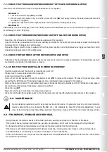
• Tighten the nuts or bolts gradually, in a “cross” pattern (see the example 

at the side);

• Tighten them, first by 30%, then by 60% and finally 100% of the maximum 

torque (see the table at the side according to EN 13611);

• Tighten each nut and bolt again clockwise at least once, until the maximum torque has been achieved uniformly;

Common procedures (threaded and flanged devices): 

• The regulator is normally positioned before the application. Previously evaluate the possibility of installing the regulator as 

shown in the installation example in 3.4;

• It can be installed in any position even if the installation shown in 3.4 (installation example) is preferred. A pressure outlet (

23

is found outside the regulator, downstream from it, to control the regulation pressure (P2);

• In STANDARD versions, it is recommended to connect the pulse outlet with a G 1/8 connection downstream of the regulator 

(see installation example) if the gas flow exceeds 40 Nm

3

/h. To do so, the cap (

29

) must be removed;

• Drain the relief valve (if present) outwards (as shown in 3.4) by removing the dust cap (

25

);

• It is always recommended to install a compensation joint;
• During installation, avoid debris or metal residues from getting into the device;
• To guarantee assembly free of any mechanical tension, we recommend using compensating joints, which also adjust to the 

pipe’s thermal expansion;

• If the device is to be installed in a ramp, it is the installer’s responsibility to provide suitable supports or correctly sized 

supports, to properly hold and secure the assembly. Never, for any reason whatsoever, leave the weight of the ramp only on 

the connections (threaded or flanged) of the individual devices;

• In any case, after installation check the tightness of the system, without subjecting the diaphragm of the regulator (therefore, 

the downstream pipe section) to a pressure higher than 300 mbar (valid only for versions with standard working diaphragm). 

For versions with reinforced diaphragm, check the tightness with a pressure equal to 1.5 times the regulator setting pressure.

Diameter

DN 25

Max. torque (N.m)

30

Summary of Contents for FRG/2MBCF

Page 1: ...one massima di esercizio Maximum operating pressure Pression maximum de fonctionnement Presi n m xima de funcionamiento P1 max 0 5 bar Attacchi filettati Threaded connections Raccords filet s Conexion...

Page 2: ...ulateurs tableau 1 Caudal de los reguladores tabla 1 Disegni Drawings Dessins Dise os 36 Caratteristiche molle di regolazione tabella 2 43 Regulation spring data table 2 Caracteristiques des ressorts...

Page 3: ...valore di taratura del dispositivo Interviene anche in caso di mancanza di alimentazione a monte Possono essere forniti anche senza dispositivo UPSO valvola di sfioro scarica all esterno piccole port...

Page 4: ...latore di pressione Versione standard Z Connessioni in linea F Connessioni a 90 IN G 1 2 R Connessioni a 90 OUT G 3 4 M Connessioni a U IN G 1 2 OUT G 3 4 3 0 MESSA IN FUNZIONE DEL DISPOSITIVO 3 1 OPE...

Page 5: ...positerondelleperevitaredanneggiamenti alle flange in fase di serraggio Durante la fase di serraggio prestare attenzione a non pizzicare o danneggiare la guarnizione Serrare i dadi o bulloni gradualme...

Page 6: ...losiva di grado continuo e come tale pu originare zone pericolose 0 come definite nella Direttiva 99 92 CE In condizioni di installazione particolarmente critica luoghi non presidiati carenza di manut...

Page 7: ...ocedere con il riarmo manuale del regolatore vedere 4 0 Chiudere il rubinetto a valle cos da portare in chiusura il regolatore il valore della P2 aumenta del valore di SG per portare l otturatore in p...

Page 8: ...e il dado di regolazione 26 finch la pressione P2 visualizzata sul manometro inizia a diminuire Lo sfioro in questo caso tarato al valore desiderato Rimuovere la chiave a tubo e chiudere il tappo 27 6...

Page 9: ...tamente il rubinetto a valle del regolatore Svitare e rimuovere il tappo 27 Premendo con chiave a tubo da 8 mm sul dado di regolazione 26 aumentare la pressione P2 al di sopra del valore preimpostato...

Page 10: ...ax Pressione massima o range di pressione di ingresso alla quale garantito il funzionamento del prodotto TS Range di temperatura alla quale garantito il funzionamento del prodotto P2 Range pressione d...

Page 11: ...when the regulator outlet pressure drops below the setting value of the device It also intervenes in the event of an upstream power failure They can also be supplied without the UPSO device relief va...

Page 12: ...sion up to 25 m3 h FRG 2MBL Z F R M Pressure filter regulator Standard version Z Connections in line F Connections at 90 IN G 1 2 R Connections at 90 OUT G 3 4 M Connections at U IN G 1 2 OUT G 3 4 3...

Page 13: ...washers inside the bolts in order to prevent damage to the flanges during the tightening stage When tightening be careful not to pinch or damage the gasket Tighten the nuts or bolts gradually in a cr...

Page 14: ...f explosive atmosphere emission of continuous degree and as such it can generate hazardous areas 0 as defined in Directive 99 92 EC In particularly critical installation conditions unattended areas po...

Page 15: ...ose the downstream valve so as to close the regulator the P2 value increases the SG value to fully close the obturator Check the tightness of the system seals and check the internal external tightness...

Page 16: ...further slowly loosen the adjustment nut 26 until the pressure P2 begins to decrease shown on the pressure gauge In this case the relief valve is set to the desired value Remove the socket spanner and...

Page 17: ...he valve downstream of the regulator Loosen and remove the cap 27 Use an 8 mm socket spanner to press the adjustment nut 26 to increase the pressure P2 above the preset value while preventing the OPSO...

Page 18: ...mum pressure or inlet pressure range that product operation is guaranteed at TS Temperature range that product operation is guaranteed within P2 Outlet pressure range Wdso OPSO calibration range that...

Page 19: ...en dessous de la valeur d talonnage du dispositif Intervient galement en cas d absence d alimentation en amont Ils peuvent aussi tre fournis sans dispositif UPSO vanne d vacuation elle d charge l ext...

Page 20: ...M Filtre r gulateur de pression Version standard Z Connexions en ligne F Connexions 90 IN G 1 2 R Connexions 90 OUT G 3 4 M Connexions U IN G 1 2 OUT G 3 4 3 0 MISE EN FONCTION DU DISPOSITIF 3 1 OP RA...

Page 21: ...r d endommager les brides pendant le serrage Pendant la phase de serrage veiller ne pas pincer ni endommager le joint Serrer les crous ou les boulons progressivement selon un sch ma en croix voir l ex...

Page 22: ...mosph re explosive en degr continu et comme tel peut cr er des zones dangereuses 0 comme d finies dans la Directive 99 92 CE En condition d installation particuli rement critique lieux non surveill s...

Page 23: ...rmement manuel du r gulateur voir 4 0 Fermer le robinet en aval afin de fermer le r gulateur la valeur de la P2 augmente de la valeur de SG pour porter l obturateur en position de fermeture totale V r...

Page 24: ...glage 26 jusqu ce que la pression P2 affich e sur le manom tre commence diminuer L vacuation est dans ce cas talonn e la valeur souhait e Enlever la cl tube et fermer le bouchon 27 6 4 R glage de la...

Page 25: ...lentement le robinet en aval du r gulateur D visser et ter le bouchon 27 En pressant avec une cl tube de 8 mm sur l crou de r glage 26 augmenter la pression P2 au dessus de la valeur pr configur e ma...

Page 26: ...onnexion P1 max Pression maximum ou plage de pression d entr e laquelle le fonctionnement du produit est garanti TS Plage de temp rature laquelle le fonctionnement du produit est garanti P2 Plage de p...

Page 27: ...tro cuando la presi n que sale del regulador desciende por debajo del valor de calibraci n del dispositivo Interviene tambi n en caso de falta de alimentaci n aguas arriba Tambi n pueden suministrarse...

Page 28: ...n Versi n est ndar Z Conexiones en l nea F Conexiones a 90 IN G 1 2 R Conexiones a 90 OUT G 3 4 M Conexiones a U IN G 1 2 OUT G 3 4 3 0 PUESTA EN FUNCIONAMIENTO DEL DISPOSITIVO 3 1 OPERACIONES ANTES...

Page 29: ...ondientes para evitar que las bridas se da en en la fase de apriete Durante la fase de apriete aseg rese de no pellizcar ni da ar la junta Apriete las tuercas o pernos gradualmente seg n un esquema de...

Page 30: ...sustancias inflamables solo de forma ocasional y concretamente El regulador puede ser peligroso respecto a la presencia en sus alrededores de otros aparatos en caso de intervenci n de la v lvula de a...

Page 31: ...el regulador v ase 4 0 Cierre el grifo situado aguas abajo para cerrar el regulador el valor de la P2 aumenta el valor de SG para cerrar completamente el obturador Compruebe la estanquidad de las jun...

Page 32: ...n P2 visualizada en el man metro empiece a disminuir El alivio en este caso est calibrado con el valor deseado Quite la llave de tubo y vuelva a cerrar el tap n 27 6 4 Regulaci n de la presi n de sali...

Page 33: ...n el punto 4 0 Cierre lentamente el grifo de la parte posterior del regulador Desenrosque y quite el tap n 27 Presionando con una llave de tubo de 8 mm la tuerca de regulaci n 26 aumente la presi n P2...

Page 34: ...ro de conexi n P1 max Presi n m xima o rango de presi n de entrada en la que se garantiza el funcionamiento del producto TS Intervalo de temperatura en el que se garantiza el funcionamiento del produc...

Page 35: ...natural 1 Gas di citt Town gas Gaz de ville Gas de ciudad 1 177 GPL LPG Gaz de p trole liqu fi Gas l quido 0 62 Tabella 1 Table 1 Tableau 1 Tabla 1 PORTATE REGOLATORI CAPACITIES OF REGULATORS D BIT D...

Page 36: ...For setting the overpressure shut off OPSO Pour talonnage blocage surpression OPSO Para calibraci n bloqueo de sobrepresi n OPSO Parte superiore regolatore dotato di sfioro Top part of the regulator...

Page 37: ...bloqueo de m nima presi n UPSO Parte superiore regolatore senza sfioro Top part of the regulator without relief valve Partie sup rieure r gulateur sans vacuation Parte superior del regulador sin aliv...

Page 38: ...di sfioro Top part of the regulator with relief valve Partie sup rieure r gulateur dot d vacuation Parte superior del regulador con alivio Per taratura sfioro For relief valve setting Pour talonnage...

Page 39: ...2c Per taratura blocco di minima pressione UPSO For setting the minimum pressure shut off UPSO Pour talonnage du blocage de pression minimum UPSO Para calibraci n bloqueo de m nima presi n UPSO Parte...

Page 40: ...Pour talonnage OPSO UPSO vacuation et raccordement en aval voir fig 2a 2b et 2c Para calibraci n OPSO UPSO alivio y conexion detr s v ase las fig 2a 2b y 2c Parte superiore regolatore con o senza sfi...

Page 41: ...tipolvere G 1 4 scarico sfioro 26 Regolazione sfioro 27 Tappo di chiusura superiore 28 Chiave speciale per taratura 29 Tappo antipolvere G 1 8 30 Tappo G 1 8 per presa impulso esterna solo su versioni...

Page 42: ...28 Cl sp ciale pour talonnage 29 Bouchon anti poussi re G 1 8 30 Bouchon G 1 8 pour prise impulsion externe uniquement sur les versions standards 2MBL ES fig 1 2 y 3 1 Regulaci n de la presi n de sali...

Page 43: ...MO 0403 1 5x29x46x6 27 37 MO 0410 1 5x29x58x7 37 65 MO 0430 2x29x49x7 65 95 MO 0460 2x29x66x7 90 170 MO 0520 2 5x29x50x7 120 190 MO 0540 2 5x29x60x7 75 170 400 MO 1320 3 5x29 8x64x9 Molle di taratura...

Page 44: ...N IN DN OUT 10 25 mbar 20 70 mbar 10 30 mbar 10 60 mbar FBCL 04 03 R 3 3 2 X Modello Compact con filtro Compact model with filter Mod le Compact avec filtre Modelo Compact con filtro IN Rp DN 25 OUT R...

Page 45: ...es department for confirmation of feasibility Le tableau reporte quelques exemples pour illustrer les possibilit s de combinaison des ressorts d talonnage entre eux Pour les mod les compact 2MBCL et s...

Page 46: ...FBCL02 03F Rp DN 15 Rp DN 20 FBL02 04F FBCL02 04F Rp DN 15 Rp DN 25 Versioni possibili con R Feasible versions with R Standard Compact IN OUT Rp DN 20 Standard Rp DN 20 Compact FBL02 03R FBCL02 03R R...

Page 47: ...ter W after the letter denoting the configuration to get the sealing washer compensation diaphragm and working diaphragm in FKM Ajouter la lettre V apr s la lettre indiquant la configuration pour obte...

Page 48: ...32 5 110 200 4 120 260 4 50 110 2 10 60 FBCL02Z 5442 5 110 200 5 200 550 4 50 110 3 60 110 FBCL02Z 5543 DN 20 1 10 25 1 20 70 1 7 20 1 5 12 FBCL03Z 1111 1 10 25 1 20 70 2 10 30 2 10 60 FBCL03Z 1122 2...

Page 49: ...90 2 10 30 2 10 60 FBL02Z 2222 3 37 65 3 50 180 2 10 30 2 10 60 FBL02Z 3322 4 65 95 4 120 260 3 20 50 2 10 60 FBL02Z 4432 5 90 170 4 120 260 4 50 110 2 10 60 FBL02Z 5442 6 120 190 5 200 550 4 50 110...

Page 50: ...0 60 FBL04Z 2222 3 37 65 3 50 180 2 10 30 2 10 60 FBL04Z 3322 4 65 95 3 120 260 3 20 50 2 10 60 FBL04Z 4432 5 90 170 4 120 260 4 50 110 2 10 60 FBL04Z 5442 6 120 190 5 200 550 4 50 110 3 60 110 FBL04Z...

Page 51: ...sono indicative non vincolanti The dimensions are provided as a guideline they are not binding Les dimensions sont indicatives non contraignantes Las dimensiones son indicativas no vinculantes Version...

Page 52: ...sono indicative non vincolanti The dimensions are provided as a guideline they are not binding Les dimensions sont indicatives non contraignantes Las dimensiones son indicativas no vinculantes Version...

Page 53: ...IT EN FR ES 53 Madas Technical Manual 4 4 2a REV 1 of 20th Feb 2020 FRG 2MBCL Z F R M FRG 2MBL Z F R M Note Note Notes Notas...

Page 54: ...ES FR EN IT 54 Madas Technical Manual 4 4 2a REV 1 of 20th Feb 2020 FRG 2MBCL Z F R M FRG 2MBL Z F R M Note Note Notes Notas...

Page 55: ...IT EN FR ES 55 Madas Technical Manual 4 4 2a REV 1 of 20th Feb 2020 FRG 2MBCL Z F R M FRG 2MBL Z F R M Note Note Notes Notas...

Page 56: ...ons le droit de toute modification technique et constructive Nos reservamos el derecho de realizar cualquier cambio t cnico y estructural Sede legale Via V Moratello 5 6 7 37045 Z A I Legnago VR Italy...

Reviews: