Page 4 of 38
MAINTENANCE PROCEDURE
Note: Maintenance can be carried out to the liquid
crystal displays and pulse output modules without
having to remove or isolate the meter from the proc-
ess line.
When maintenance to any other part of the meter is
required, the meter must be isolated and the line
pressure released.
Refer to the exploded parts diagram on (see Fig
for
item numbers.
Note: It is advisable to mark all components with a
marker pen before disassembly, to ensure all the
components are replaced to their correct position
during the reassembly process.
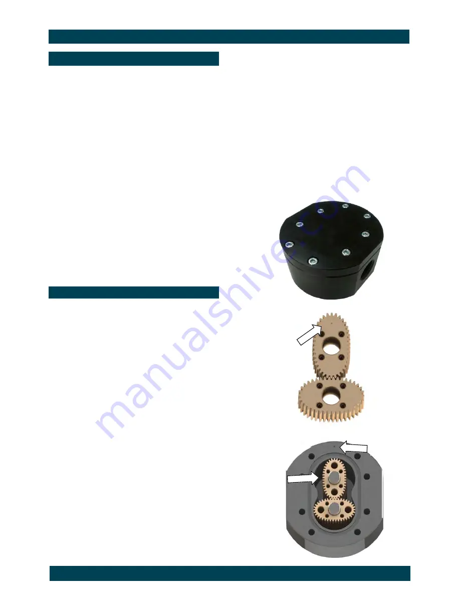
1. Remove the meter cap by loosening the bolts on
the underside of the meter body. (see FIG 1)
2. Remove the O-Ring from the O-Ring groove in the
meter cap.
Wipe clean of grease and store in clean place
3. Remove rotors from the meter body
4. Remove the shafts from the meter body.
DISASSEMBLY
REASSEMBLY
1. Before reassembling check the condition of the
rotors (replace if necessary).
2. Replace the shafts into the meter body.
3. There are two Rotor Types. Active and Neutral.
The Active Rotor is fitted with the magnets. They
can be identified by running a metal object over
the face of the rotor (smooth side)
Caution: The active rotor is always fitted
nearest ‘dimple’ on the meter body
(see FIG 3)
Replace Active Rotor.
Check the smooth side of the rotor is the leading
face when fitting onto the shaft and into the meter
body. (see Fig 2).
Replace Neutral Rotor. Check that the smooth
side of the rotor is the leading face when fitting
onto the shaft. (see FIG 2)
Fit the neutral rotor onto the shafts ensuring that
the rotor pair are at 90 degrees to one another.
(see FIG 3)
Check their operation by turning either of the
rotors. If the rotors are not in mesh correctly,
or do not move freely, remove one of the rotors
and replace correctly at 90 degrees to one
another.
4. Smear the O-Ring with a light film of grease.
Replace the O-Ring into groove in the meter cap.
The O-Ring will need to be replaced if it has
grown or is damaged in anyway.
5. Replace the meter cap.
6. Insert the cap head screws and tighten in a
diagonal sequence 1, 5, 7, 3, etc.
(see Meter Torque Ratings, page 15)
7. Test the meter by turning the rotors with a finger
or by applying very low air pressure (no more
than a good breath) to one end of the meter,
before returning the meter to service.
Rotor Face
Smooth side
FIG 2
FIG 1
FIG 3
Dimple
Active Rotor
Summary of Contents for MX06S
Page 22: ...Page 22 of 38 PRESSURE DROP v VISCOSITY 100 50 25 10 5 100 50...
Page 25: ...Page 25 of 38 WALL MOUNT ADAPTOR Series MX12 Aluminium Wall Mount bracket to suit model MX12...
Page 26: ...Page 26 of 38 WALL MOUNT ADAPTORS Series MX19 Aluminium Wall Mount bracket to suit model MX19...
Page 27: ...Page 27 of 38 WALL MOUNT ADAPTORS Series MX25 Aluminium Wall Mount bracket to suit model MX25...
Page 28: ...Page 28 of 38 WALL MOUNT THREAD POSITION Series MX40 Wall mount thread positions for MX40...
Page 29: ...Page 29 of 38 WALL MOUNT THREAD POSITION Series MX50 Wall mount thread positions for MX50...
Page 31: ...Page 31 of 38 DIMENSIONS MX75 with Air Eliminator 3 Flange 3 Threaded Connection...
Page 33: ...Page 33 of 38 DIMENSIONS MX100 with Air Eliminator 4 Flange 3 Threaded Connection...
Page 34: ...Page 34 of 38 NOTES...
Page 35: ...Page 35 of 38 NOTES...
Page 36: ...Page 36 of 38 NOTES...


