background image

56

X.200

Digital X Bus

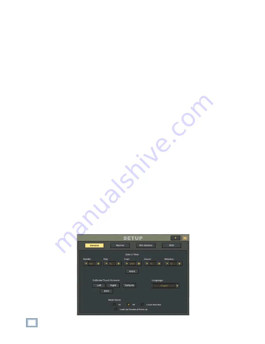
Setup Window

The Setup Window (Windows > Setup) is very im-

portant to the functionality of the Digital X Bus. Its 
settings determine how the console operates within 
its own architecture as well as how it interfaces 
with other digital equipment. 

Follow the checklist below to verify that each 

Setup Window parameter is intentionally set. For 
specifi c recommendations for various parameter set-
tings, refer to “Setup” on page 31.

Setup window settings are automatically stored 

and are recalled in subsequent boot-ups.

 General


•  Date and Time


•  Touch Calibration


•  Language


•  Smart Save


•  Create New Files


•  Load Last Session at Power-up

 Macros


•  User-defi ned Screen Sets

 Mix 

Options


•  Surround Mode

•  Mixing Options (One Button Record, Record 

Safe, Song Offset, Solo Latch, Use Pre-Roll, 
Pre-Roll time, Meters, Show All Meters, 
Peak Hold, Footswitch Assignment)

❏ 

MIDI


•  MIDI File Tempo Map


•  Default Tempo


•  MIDI Device ID's


•  MTC In


•  MMC Out


•  MIDI Map In/Out


•  DAW Main In/Out


•  DAW Ext 1 In/Out


•  DAW Ext 2 In/Out

Connecting Input Sources

❏ 

Install three MIC/LINE 4 or MIC/LINE 8 cards 
into the Digital X Bus A•SLOTS (or whatever 
cards you choose to use for the inputs to the 
Digital X Bus).

  Using appropriate cable, connect your micro-

phones and line-level signal sources to the mic- 
or line-level inputs.

 Connecting Analog Multitrack(s)

  For 24-track recording, install three LINE cards 

into the Digital X Bus B•SLOTS.

  Using the appropriate cable, connect the 25-pin 

D-Sub OUT connectors on the LINE cards to the 
multitrack inputs.

  Using the appropriate cable, connect the multi-

track outputs to the 25-pin D-Sub IN connectors 
on the LINE cards.

  Make sure all connections are tightly secured.

Summary of Contents for X.200

Page 1: ...OWNER S MANUAL X 200 Manual Rev 1 0 4 March 7 2005...

Page 2: ...ise induced hearing loss but nearly everyone will lose some hearing if exposed to sufficiently intense noise for a period of time The U S Government s Occupational Safety and Health Administration OSH...

Page 3: ...SERIAL9PIN 13 11 MIDIINandOUT 13 12 ETHERNET 13 13 USB 13 14 IECPowerReceptacle 13 15 PowerSwitch 14 MoreConnections 14 16 Mouse 14 17 Keyboard 14 18 USB 14 19 VideoCard 14 ConsoleSurfaceControls 15...

Page 4: ...25 Paste Ctrl V 25 ModifyLevels 25 InsertGlobalTime 26 DeleteGlobalTime 26 ClearAutomation 26 HistoryList Ctrl H 26 ClearHistory 27 CopyMixToBus 27 TheChannelMenu 27 ChannelSettings Ctrl B 27 ChannelP...

Page 5: ...stallationandConnectionofOptionalI OCards 52 Anti StaticPrecautions 53 InstallationProcedure 53 I OCards 54 1 MIC LINE4CARD 54 2 MIC LINE8CARD 54 3 LINECARD 54 4 DIGITALCARD 54 5 AES EBUCARD 54 6 FIRE...

Page 6: ...TypesofAutomation 73 WhereDoIStart 73 TimeCodeFromPlaybackDevice 74 Start Automation 74 TrimLevels 75 AutomateEQ Dynamics andEffects 75 EditingAutomation 75 AppendixA ServiceInformation 76 WarrantySer...

Page 7: ...al Don t forget to visit our website at www mackie com for more information about this and other Mackie products AppendixD SoftwareInstallation 88 DigitalXBusSoftwareInstallationProcedure 88 WindowsXP...

Page 8: ...sole The Digital X Bus offers you the flexibility to config ure it for virtually any recording application through its extended card cage and I O routing options And it was designed with the ability t...

Page 9: ...d to use DB25 cables that breakout to XLR 1 4 TRS or TT connectors Once you ve unpacked your new Digital X Bus you ll want to posi tion it where you can sit comfort ably and reach the touchscreens and...

Page 10: ...kHz sample rates the S MUX protocol is used to provide four channels of I O on the A connectors and four channels of I O on the B connectors At 176 4 192 kHz sample rates the S MUX II protocol is use...

Page 11: ...nment drop down boxes Even though the stereo AES EBU input is intended for a digital two track return you can assign them to feed channels buses the control room or whatever you like S PDIF IN and OUT...

Page 12: ...udio specifications include the presence of a clock refer ence signal through the same physical connection as the audio signals This means that you can use the Digital X Bus as a master clock source a...

Page 13: ...ontrol Surface It is up to you to route the MIDI functions of the console to from the physical MIDI port using the MIDI Patch Bay in the Setup window Windows Setup MIDI If you need additional MIDI por...

Page 14: ...rd The video card has two connectors one for each touchscreen The upper connector is a VGA type and connects to the left touchscreen while the lower connector is a DVI type and connects to the right t...

Page 15: ...9 10 and 11 12 Send AUX 9 10 and 11 12 PAN Digital TRIM LEVEL TO TAPE Channel Strip The touchscreens are actually an extension of the channel strips so we ll begin by describing the channel strip con...

Page 16: ...red for that channel When WRITE is selected the ASSIGN buttons determine which channels can be written to au tomation A channel must be Write enabled and the BYPASS button turned off in the AUTOMA TIO...

Page 17: ...5 Adjust the listen ing level of the Near or Main outputs with the knob 36 in the Control Room sec tion on the console or the Near Main control in the Con trol Room Setup win dow The DIM button 37 all...

Page 18: ...e the timeline cursor in the Mix Editor and the position display to the Edit Out point Click Talk to Phones 1 to send the talkback sig nal to the Phones 1 output and Talk to Phones to send the talkbac...

Page 19: ...e timeline cursor in the Mix Editor to the point where you want to stop looping Press STORE 55 and then STOP 53 You can also click and drag the Loop In and Loop Out markers in the time bar in the Mix...

Page 20: ...Digital X Bus via MMC You can however press Play on your recorder and as soon as time code is received the Digital X Bus reverts to PLAY mode 59 REWIND Engages external machine and the time code displ...

Page 21: ...ning graphic display to open the Surround window Click in the Panning graphic display to adjust the surround position The touchscreens provide an elegant user inter face for accessing and controlling...

Page 22: ...lternatively hold down the ALT button or ALT key and press a channel SELECT but ton to lock and unlock a channel Select Reset All to change all the channel strips back to their original configuration...

Page 23: ...Use this to open a pre existing session file As soon as the session is opened the faders and all other parameters move to their proper settings for the current time code location Save Session Ctrl S P...

Page 24: ...kages Opens the Package Installer window Scans any attached USB peripheral for a Mackie packaged installation file Reports the status of all installers detected Used for all Mackie approved plug in an...

Page 25: ...t Ctrl H Clear History Copy Mix To Bus Undo Ctrl Z Reverses an action If you ve made a bad automation pass cut something you didn t re ally want to cut pasted somewhere you didn t want to paste etc si...

Page 26: ...ength of time inserted Delete Global Time With the Mix Editor open this feature globally deletes a region of data change at the selected start point on all channels for all data Selecting Delete Globa...

Page 27: ...ms from the History window This action cannot be undone Copy Mix To Bus Copies the current L R mix to a pair of buses Selections include Bus 1 and 2 Bus 3 and 4 Bus 5 and 6 or Bus 7 and 8 Check Unassi...

Page 28: ...e pans linked inversely This means that rotating the pan control on one channel causes the pan control on the linked channel to rotate in the opposite direction UnLink Channels Ctrl U Removes a link b...

Page 29: ...at default settings Select Fader Bank Alt A Selects all 24 channels in the currently selected fader bank for clipboard automation and other operations pertaining to multiple channel modi fications Se...

Page 30: ...s Write Flyback This determines what happens to the parameter levels upon punch out of automation record When Write Flyback is selected a checkmark appears next to Write Flyback in the Automa tion sub...

Page 31: ...channel strip These options have no effect on the meter bridge at the top of the screen In Displays the signal level at the input to the compressor Reduction Displays the amount of gain reduction bei...

Page 32: ...outputs from the selected bank to 24 consecutive outputs Outputs 1 24 Routes and assigns the outputs for the cur rently selected bank to hardware outputs 1 24 Cards 1 3 Outputs 25 48 Routes and assig...

Page 33: ...ouchscreen isn t responding as quickly as it should Language selection is a drop down box used to select your preferred language English is the default setting Smart Save is a function that automatica...

Page 34: ...ether Ideally Pre roll is equal to the sync lock time for the recording system s transports so that synchronized playback is a reality by the time the devices roll past the locate position Song Offset...

Page 35: ...Ts DA Series or other multitrack recorders A unique ID is required for using MMC MIDI Machine Control with multiple recording devices The following boxes select the MIDI port s used to send and receiv...

Page 36: ...ode enter WRITE mode and with one move increase the vocal track fader 2 dB throughout the duration of the pass Trim From Unity When this is checked selecting Trim or Touch mode causes the faders to ju...

Page 37: ...mines the amount of time between when the control stops moving and when automation stops writing data for that parameter The range for Return Time is 0 ms to 5000 ms 5 sec Snapshots Ctrl 2 A snapshot...

Page 38: ...nter Locator SMPTE Position Double click in the desired field Hours Min utes Seconds Frames and click and hold in the upper half of the field to scroll the number up or click and hold in the lower hal...

Page 39: ...stored settings Ideal for making quick A B comparisons be tween EQ settings MORPH Click the MORPH button to smoothly fade from one memory setting to the other Memory A and B The amount of time it take...

Page 40: ...increases linearly until the threshold point is reached After that point the output level no longer increases linearly Instead it increases at a reduced rate determined by the ratio setting The compr...

Page 41: ...output signal level leaving the compressor OUT and one indicates the amount of gain reduc tion being applied to the signal R The gain reduc tion meter indicates from the top to the bottom starting at...

Page 42: ...in any mixing panorama along with individual subwoofer level and depth of center control Surround position control is available from the control surface by using the individual channel PAN L R and PAN...

Page 43: ...urround controls to their default settings MORPH Click the MORPH button to smoothly fade from one memory setting to the other Memory A and B The amount of time it takes for this transition is set in t...

Page 44: ...nal You can use any I O card s input Phase Reverse Click the Phase Reverse button to invert the polarity of the signal by 180 Digital Trim The Digital Trim allows you to adjust the input level just af...

Page 45: ...ion Used to insert a plug in effect into the channel post DSP Click the Post Insert drop down box to select a plug in from the available effects in the Effects Rack Note One or more plug ins must be i...

Page 46: ...n box or you can view mul tiple channels of one parameter type by selecting All Channels and the parameter type in the second Show drop down box Automation Event curves are displayed as dots actually...

Page 47: ...ted region Select Delete Time to delete a selected region of data Play From Selection starts playback of automa tion from the time entered in the Start Time window at the top of the Mix Editor The sta...

Page 48: ...ll The right pointing arrow button next to the Magnify tool toggles Auto Scroll on and off You can toggle Auto Scroll while time code is running Nudge Arrows Click the Nudge Arrows button to open the...

Page 49: ...r as Reverb 1 and Reverb 2 Delete Plugin Click this drop down box to select a plug in to remove from the Effects Rack Deleting a plug in from the Effects Rack auto matically removes it from its input...

Page 50: ...able control is selected under MIDI Type Mode The Mode option is enabled when Note is selected as the MIDI Type The two options available are Normal and Toggle These refer to how the switch responds t...

Page 51: ...the Tools submenu Au dio Toolbox and System Info Audio Toolbox Ctrl T The Audio Toolbox has a built in spectrum ana lyzer and setup for three built in oscillator sources The spectrum analyzer allows y...

Page 52: ...ackie HR824s In addition set up the system in an acous tically controlled and balanced environment Avoid a control room with identical dimensions in any direc tion and set it up with a good mixture of...

Page 53: ...TS Note Do not remove or reposition the two cards that come with your Digital X Bus The D slot is not used on the X 200 and is described in the Digital X Bus X 400 manual 4 Now is the time to install...

Page 54: ...sometimes referred to as lightpipe This connection provides eight channels of digital audio You can purchase this cable from your Alesis dealer Monster Cable Hosa or other cable manufacturer The conne...

Page 55: ...ified Open and load a snapshot or a session optional It s a good idea to keep a snapshot of each working configuration as a starting point track ing overdubs symphony grunge band etc Connect all mics...

Page 56: ...cord Record Safe Song Offset Solo Latch Use Pre Roll Pre Roll time Meters Show All Meters Peak Hold Footswitch Assignment MIDI MIDI File Tempo Map Default Tempo MIDI Device ID s MTC In MMC Out MIDI Ma...

Page 57: ...source should be connected to the SYNC card BNC WORD CLOCK IN and the Sample Clock setting should be set to Word Clock BNC in the I O Configuration window Windows I O Configuration Word Clock Setup Mu...

Page 58: ...o Out puts 25 48 Options Bank to Outputs Out puts 25 48 This routes all 24 inputs on Fader Bank 1 to the SLOT B Outputs going to the multitrack recorder s Configure Auxes for desired Pre Post status S...

Page 59: ...t or cold adjust level with the LEVEL TO TAPE control Direct Out Level in the ASSIGN win dow CUE 1 CUE 2 MIC LINE POT CONTROLS PAN L R PAN F B 7 8 5 6 3 4 1 2 TRIM PAN PAN 9 10 11 12 LEVEL TO TAPE If...

Page 60: ...e internal effects in the ASSIGN window Adjust the channel aux levels to route channels to outboard effects Verify that the MIX OUT is connected to the mixdown machine A B MIX OUT CARD SPDIF SPEAKERS...

Page 61: ...61 Owner s Manual Owner s Manual...

Page 62: ...n the peaks With channel faders off set the Master Fader at unity U The signal at the SPEAKERS A and SPEAK ERS B output is determined by the Control Room Source selection in the Control Room Section S...

Page 63: ...M G MAN F FIGURE E P PAT ATENT P T PENDING ENGINEERED BY D BY SYNC C SLOTS D SLOT B SLOTS A SLOTS MIDI IN FOOT SWITCH 1 2 MIDI OUT USB ETHERNET SERIAL 9 PIN 1 15V 9 V 9amp 6 p 60Hz 230V 4 5 V 4 5amp 5...

Page 64: ...eft corner and select an effect from the list of avail able plug ins in the NEW PLUGIN window then click OK 3 You can select the same plug in multiple times They appear as consecutively numbered effec...

Page 65: ...el s signal path Note See the instruction manuals for your plug ins for specifics on individual functionality DynamicsandEQApplications Dynamics and equalization are typically applied in one of two wa...

Page 66: ...00 with a USB MIDI interface However because the X 200 USB port and a computer s USB port are both con figured as hosts which are designed to connect to a USB port configured as a device like a USB MI...

Page 67: ...e they only output the next sample when the master device outputs the next sample This type of system provides very accurate synchronization Incorporating a time reference like MTC along with sample a...

Page 68: ...Bus is set to Internal in the Clock Card Setup window it generates word clock as a master device All other devices must be connected as slaves Tip A quick way to open the Clock Card Setup window is to...

Page 69: ...ice and so on This is the most efficient manner to check out a system Verify connection integrity and quality of all sync cables Verify a consistent sample rate setting on all connected sync devices a...

Page 70: ...rd to the SMPTE I O on the digital audio interface to provide time code communication 4 Connect the two 4x4 USB MIDI interfaces together via their MIDI IN and OUT connectors and connect one to the USB...

Page 71: ...T SWITCH 1 2 MIDI OUT USB ETHERNET SERIAL 9 PIN 1 15V 9 V 9amp 6 p 60Hz 230V 4 5 V 4 5amp 5 p 50Hz 1100 1100W M W Max Bass Guitar Direct Box Electric Guitar From Aux Sends Channel Inserts or Master In...

Page 72: ...drum cymbals left cymbals right tom 1 and tom 2 You can free up five extra tracks by bouncing these down to one track or free up four extra tracks if you want to bounce them down to a stereo pair of...

Page 73: ...through snapshots Each of these snapshot changes record into the sequence Play the sequence back with the D8B receiving MIDI playback at its MIDI input Snapshots will playback in the same time and ord...

Page 74: ...tted the Digital X Bus control surface position readout window upper right corner of screen will scroll MTC You will see a continuous increase of Hours Minutes Seconds and Frames If you see this scrol...

Page 75: ...fore attempting the automation pass Each time you perform a new automation pass new data combines with the old in a seamless manner Continue building the mix until every thing is just right Trim Level...

Page 76: ...all the audio equip ment into the same AC circuit so they share a common ground Warranty Service Details concerning Warranty Service are spelled out in the Warranty section on page xx If you think yo...

Page 77: ...number Service Request Number and a detailed description of the problem including how we can duplicate it 5 Write the Service Request Number in BIG PRINT on top of the box Units sent without a Servic...

Page 78: ...earth connection at the unbalanced input In most cases the balanced ground earth will also be connected to the ground earth at the unbalanced input If there are ground loop prob lems this connection m...

Page 79: ...rs They are also the same pinout as the analog cards for the Mackie D8B and hard disk recorders 1 2 3 4 5 6 7 8 9 10 11 12 13 14 15 16 17 18 19 20 21 22 23 24 25 HOT COLD GROUND HOT COLD GROUND HOT CO...

Page 80: ...I O measurements are the same for any analog con nection on any Card All digital I O measurements are the same for any digital con nection on any Card 44 1 kHz 48 kHz SR Mic Line In to Line Out 246 sa...

Page 81: ...D OUTPUT 0 dBFS 24 4 dBu 0 2 dB Frequency Response Reference signal 1 kHz 4 dBu Analog Line Card Input to Analog Line Card Output 44 1 kHz 0 1 dB 20 Hz 20 kHz 48 kHz 0 05 dB 20 Hz 20 kHz 88 2 kHz 0 15...

Page 82: ...82 X 200 Digital X Bus...

Page 83: ...nd Masters Talkback Mic Oscillators x 72 x 8 x 12 x 3 SOFTWARE INPUT SOURCES Channel Input Source x72 Digital Trim Channel Delay 0 500ms Solo Bus Channel Mute Hardware Output Hardware Input ASSIGNMENT...

Page 84: ...84 X 200 Digital X Bus VST EFFECT S AUX SEND MASTER CHANNEL INSERT SEND BUS INSERT SEND CHANNEL INPUT CHANNEL INSERT RETURN BUS INSERT RETURN x 72 x 12 x 10 x 72 x 72 x 10...

Page 85: ...sert Return Pre DSP Insert Post DSP Bus Insert EQ Comp Lim Gate Exp Bus DSP Bus Fader Pre Fader Meter Post Fader Meter BUS AUX ASSIGNMENT Channel Input Bus Assign Hardware Destination Software Patch C...

Page 86: ...PE T OUT PFL SOLO PAN AUX 11 12 PLUG INS ONLY PLUG INS ONLY CHANNEL OUT TO CHANNEL METER INPUT TO CHANNEL METER PRE FADER TO CHANNEL METER POST FADER CHANNELS x72 BUSES x8 AUX SEND MASTERS x12 AUX RET...

Page 87: ...UG INS ONLY TO CHANNEL METER INPUT CHANNEL METER FROM INPUT FROM PRE FADER FROM POST FADER CTRL PRE INSERT SEND PRE INSERT RETURN CTRL POST INSERT SEND POST INSERT RETURN FADER TO CHANNEL METER POST F...

Page 88: ...asked to shut down the Digital X Bus application in order to run the Installer 10 Once you are back to the main mixer screen re select the Install Packages from the File Menu 11 If there is a System...

Page 89: ...inzip com and installed on your PC USB Flash Pen Drive Method recommended Requires a USB Flash Pen drive with the appropriate drivers for Windows 2000 ME 98SE 1 Download the Digital X Bus software upd...

Page 90: ...ital X Bus application in order to run the Installer 13 Once you are back to the main mixer screen re select the Install Packages from the File Menu 14 If there is a System Update file in the list and...

Page 91: ...USB CD ROM drive attached to your Digital X Bus 7 Select Install Packages from the File Menu on the Digital X Bus 8 Select the new build to be installed from the list and select Run Installer Select O...

Page 92: ...er on your desktop that has the same name as the Digital X Bus Software Update file 3 Open that same folder so you can see all the contents and files 4 Insert a blank CD into your Mac s CD Drive and c...

Page 93: ...93 Owner s Manual Owner s Manual...

Page 94: ...94 X 200 Digital X Bus Index...

Page 95: ...95 Owner s Manual Owner s Manual...

Page 96: ...rk of Steinberg Media Technologies GmbH The following are trademarks or registered trademarks of LOUD Technologies Inc The Mackie logo V Pot HUI the Running Man figure and Digital X Bus All other bran...

Page 97: ...horized service centers and deemed eligible for repair or replacement under the terms of this warranty will be repaired or replaced within thirty days of receipt LOUD Technologies and its authorized s...

Page 98: ...ed Road NE Woodinville WA 98072 USA www mackie com sales mackie com United States and Canada 800 898 3211 Europe Asia Central and South America 425 487 4333 Fax 425 487 4337 Middle East and Africa 31...

Reviews: