15
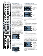
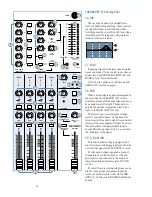
3. INSERT
With nothing plugged into this jack, the
channel’s signal goes straight through the mic/
line preamp to the channel strip. With an ex-
ternal effects device plugged into this jack, the
channel’s signal leaves the mixer, goes through
the effects device and back into the channel
strip.
Use these jacks to send the channel signal
through a compressor, graphic equalizer or
similar device. Since the insert is before the
CHANNEL FADER (42), moving that fader will
not alter the level sent to a compressor,
thereby preserving the original signal’s charac-
teristics.
These unbalanced jacks are wired thusly:
Tip = Send (to effects device input)
Ring = Return (from effects device output)
Sleeve = Common ground (connect shield
to all three sleeves)
Specialty “Y” cables, developed just for these
jacks, are widely available.
Besides being used for inserting effects de-
vices, these jacks can also be used as channel
direct outputs; post-TRIM, pre-LOW CUT and
pre EQ.
Here are three ways to use the INSERT
jacks:
EFFECTS: SERIAL OR PARALLEL?
Effects devices are used
either in serial or in parallel:
Serial
means that the en-
tire signal is routed through
the effects device. Examples
include: preamps, compres-
sor/limiters, graphic equalizers. Connections
are typically made via the channel insert jacks.
Parallel
means that a portion of the signal
is tapped off to the effects device processed
and returned, to be mixed with the original
“dry” signals. Multiple signals (via multiple
mixer channels) can all make use of the same
parallel effects device. Examples include:
reverb, delay, chorus. Connections are typically
made via aux sends & aux returns.
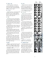
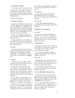
4. STEREO LINE IN
These balanced inputs are designed for TRS
balanced or TS unbalanced signals, from -20dB
to +20dB. They can accept any line-level in-
strument, effects device or tape player.
When connecting a stereo device (two
cords), use the LEFT (MONO) input and the
RIGHT input.
When connecting a mono device (just one
cord), always use the LEFT (MONO) input and
plug nothing into the RIGHT input. A trick
called “jack normalling” will cause the signal to
appear on both sides.
These inputs accept 1/4” TRS balanced and
1/4” TS unbalanced plugs, see the previous
page for wiring details.
Direct out with no signal interruption to master.
Insert only to first “click”
Channel Insert jack
Channel Insert jack
Channel Insert jack
Direct out with signal interruption to master.
Insert all the way in to the second “click”
For use as an effects loop.
(TIP = SEND to effect, RING = RETURN from effects)
MONO PLUG
MONO PLUG
STEREO
PLUG
“tip”
This plug connects to one of the
mixer’s Channel Insert jacks.
“ring”
tip
ring
sleeve
SEND to processor
RETURN from processor
(TRS plug)
Dry Signal
Serial Device
Processed
Signal
Insert
Send
Insert
Return
Dry Signal(s)
Dry Signal(s)
Aux
Send
Aux
Return
Wet Signal
Channel Path
Mix
Stage
Output
Section
Processed
Signal
Signal Processor
(e.g., Compressor)
Signal Processor
(e.g., Reverb)
Parallel Device


