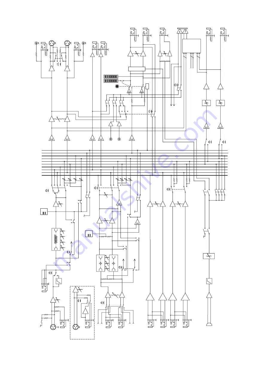
background image

32

   Onyx 1220i

L

R

Aux 1 (post)

Aux 2 (post)

Solo(PFL)

SoloLogic

Main

L/3

R/4

Alt

Aux 1 (pre)

Aux 2 (pre)

L

R

Aux 1 (post)

Aux 2 (post)

Solo(PFL)

SoloLogic

Main

L/3

R/4

Alt

Aux 1 (pre)

Aux 2 (pre)

Solo logi

c

Control  Room


leve

l

Main level

Aux Return 

2

L

R

Inser

t

HP

F

Solo

Le

ve

l

Pa

n

So

lo

Leve

l

Aux Send

s

Pa

n

Leve

l

Tape

Le

ft

Righ

t

Left/3

Right/

4

Aux 1 

Ou

t

Au

x 2 Ou

t

Au

x 1 leve

l

Phones

Contro

l

Room Ou

t

L

R

L su

m

R su

m

Al

t L/3 su

m

Alt R/4 su

m

Aux 1 su

m

Aux 2 

su

m

Solo su

m

Leve

l

Aux Return 

1

L

R

LO

MI

D

80

10

0~8K

12

K

HI

Aux 

1

Tape

Me

te

r

CD/Tape in

L

R

RU

DE

SOLO LE

D

Bal/Unba

l

Bal/Unba

l

Ba

l

Ba

l

Talkback Assign

Alt3/4

CD/Tap

e

Ma

in

C/R Sourc

e

3-Ban

dE

Q

Phones


le

ve

l

Au

x 2 leve

l

Aux 

2

to Phones

to Aux1-2

Firewire I/

O

FW

 13-1

4

C/

di

m

Channel 1-12

dire

ct

 out

s

Fire

wire


outputs 

Alt 3/

4

Ma

in

 L/

R

Al

t 3/

4

Ma

in

 L/

R

to Au

x1

to Main L/

R

pos

t

pr

e

pos

t

pr

e

Firewire1-2 to 

C/

R

of

f

C/R to 

Ma

in

of

f

Lo

Cu

t

By

pa

ss

Talkback

NOTE: Switches are shown in the default (out) position.

Mi

le

ve

l

+4dB

u

C/R 

L

C/

R  R

 Alt ou

t

Main Ou

t

48

V

Mono 

Channels 1-

4

Mic

Lin

e

Gain

+

-

Mic:

 0 ~ +6

0d

B

Line

: -2

0 ~ +

40dB

Hi

-Z

Line

Hi-

Z

+

-

Line

Ch 1-2

3-Band EQ

LO

80

2.

5K

12

K

HI

MI

D

LO

80

2.

5K

12

K

HI

MI

D

PK -2

0

PK -2

0

Internal


Talkback mi

c

Leve

l

Stereo


Channels

5-12

L

R

FW

Line

Input from FW 1 re

t

Input from FW 2 re

t

(Ch.

11

-1

on

ly

)

(Ch.

11

-1

on

ly

)

(Ch.

11

-1

on

ly

)

 To FW

FW

 Ta

p

FW Ta

p

To FW

To FW

-2

0 ~ +2

0d

B

Gain

Mic

75Hz

Po

st

Pr

e

Mod Pt

Mo

d Pt

Mo

Pt

Po

st

Pr

e

Mod Pt

Mo

Pt

Mo

Pt

FW 1-12

FW 15

-1

6

FW 1-2 

to


Ch

 11-1

2

Phan

to

m

NOTE: Modifications (marked MOD above) must be undertaken by authorized LOUD service centers onl

y

Block Diagram

Summary of Contents for ONYX 1220i

Page 1: ...U 15 15 U 15 15 U 15 15 EQ MID 2 5kHz LOW 80Hz HIGH 12kHz EQ MID 2 5kHz LOW 80Hz HIGH 12kHz MID 2 5kHz LOW 80Hz HIGH 12kHz PRE POST SEND 1k 100 8k HIGH 12kHz U 15 15 LOW 80Hz EQ AUX 2 1 L R PAN 1 LIN...

Page 2: ...adian Department of Communications ATTENTION Le pr sent appareil num rique n met pas de bruits radio lectriques d passant las limites applicables aux appareils num riques de class A de class B selon l...

Page 3: ...when making connections pressing solo or doing anything that may cause loudness in the head phones This will help protect your hearing Always turn down the main mix level and con trol room level when...

Page 4: ...With both aux sends routable to your DAW the 1220i allows you to use your favorite plug in as a realtime ef fect Just route an aux send to your DAW apply the plug in and assign your DAW outputs to th...

Page 5: ...marks infor mation that is critically important or unique to the mixer For your own good read them and remember them This icon will lead you to some explanations of features and practical tips Go ahea...

Page 6: ...E OR FW 1 2 18 24 HIGH EQ 19 25 MID EQ FREQUENCY CH 1 4 19 26 MID EQ LEVEL CH 1 4 19 27 MID EQ LEVEL CH 5 12 19 28 LOW EQ 19 29 AUX SEND 1 AND 2 20 30 PAN 20 31 MUTE SWITCH AND ALT 3 4 20 32 20 AND OL...

Page 7: ...1 L R PAN MAX MAX 2 3 4 7 8 5 6 AUX 2 1 L R PAN MAX MAX AUX 2 1 L R PAN MAX MAX AUX 2 1 L R PAN MAX MAX 9 10 11 12 LINE IN 9 10 LINE IN 11 12 LINE IN 7 8 LINE IN 5 6 MID FREQ U 15 15 U 15 15 1k 100 8k...

Page 8: ...E POST SEND EQ MID 2 5kHz HIGH 12kHz PRE POST SEND L L L L R R R R SEND INPUT MONO MONO MONO MONO R 4 L 3 L R L R POWER MIC 1 2 75Hz 18dB OCT 3 75Hz 18dB OCT 4 PRE POST SEND PRE POST SEND GAIN GAIN GA...

Page 9: ...FREQ 1 FIREWIRE L R POWER 4 3 CHANNEL INSERT BAL UNBAL 1 AUX RETURN 2 2 1 1 PRE FADER PRE EQ TIP SEND RING RETURN BAL UNBAL 2 MAIN OUT BALANCED AUX SEND L R L R Electronic Drum Kit Computer with audio...

Page 10: ...ND EQ MID 2 5kHz HIGH 12kHz PRE POST SEND L L L L R R R R SEND INPUT FW 1 2 LINE MONO MONO MONO MONO R 4 L 3 L R L R POWER MIC 1 2 75Hz 18dB OCT 3 75Hz 18dB OCT 4 ONYX MIC PRE PRE POST HI Z LINE SEND...

Page 11: ...s and iTunes as intermission music or examples of how the practice sessions should really sound These same two channels from the computer can also be chosen as inputs to channels 11 and 12 allow ing y...

Page 12: ...h built in power amplifiers Aux send 1 and aux send 2 are independent of each other so you can set up two separate aux mixes The aux 1 send signal is the sum mix of all the channels whose aux 1 send c...

Page 13: ...n plug in almost any kind of mic that has a standard XLR type male mic con nector dB 30 20 10 40 50 5 5 U 60 10 O O 10 dB 30 20 10 40 50 5 5 U 60 O O ALT 3 4 10 dB 30 20 10 40 50 5 5 U 60 O O ALT 3 4...

Page 14: ...utputs if tape is selected Alt 3 4 outputs if alt 3 4 is selected A 2 track FireWire feed from your computer if FW 1 2 is selected A combination of all four above Except for main mix whatever is playi...

Page 15: ...GAIN GAIN 40dB U 20dB U 20 30 40 60 40dB U 20dB U 20 30 40 60 40dB U 20dB U 20 30 40 60 40dB U 20dB U 20 30 40 60 U 15 15 U 15 15 U 15 15 U 15 15 EQ MID 2 5kHz LOW 80Hz HIGH 12kHz EQ MID 2 5kHz LOW 80...

Page 16: ...0 OL 20 OL 20 OL 20 OL 20 SOLO SOLO SOLO SOLO SOLO SOLO SOLO SOLO MUTE MUTE MUTE MUTE MUTE MUTE MUTE MUTE 48V 48V 48V 48V U 15 15 U 15 15 ONYX MIC PRE TALKBACK MAIN MIX TALKBACK PRE POST HI Z LINE PRE...

Page 17: ...15 U 15 15 U 15 15 EQ MID 2 5kHz LOW 80Hz HIGH 12kHz EQ MID 2 5kHz LOW 80Hz HIGH 12kHz MID 2 5kHz LOW 80Hz HIGH 12kHz PRE POST SEND 1k 100 8k HIGH 12kHz U 15 15 LOW 80Hz EQ AUX 2 1 L R PAN 1 LINE 2 L...

Page 18: ...se the left sides of the knobs cut as well as the right boost If you find yourself repeatedly using a lot of boost or cut consider altering the sound source such as placing a mic differently trying a...

Page 19: ...20 10 40 50 5 5 U 60 O O ALT 3 4 10 dB 30 20 10 40 50 5 5 U 60 O O ALT 3 4 10 dB 30 20 10 40 50 5 5 U 60 O O ALT 3 4 OL 20 OL 20 OL 20 OL 20 OL 20 OL 20 OL 20 OL 20 SOLO SOLO SOLO SOLO SOLO SOLO SOLO...

Page 20: ...ake the sound appear much louder when panned center 31 MUTE switch and ALT 3 4 The dual purpose mute alt 3 4 switch is a Mackie signature When Greg was designing our first product he had to include a...

Page 21: ...15 15 1k 100 8k HIGH 12kHz U 15 15 LOW 80Hz EQ AUX 2 1 L R PAN MAX O O MAX O O MID FREQ U 15 15 U 15 15 1k 100 8k HIGH 12kHz U 15 15 LOW 80Hz EQ AUX 2 1 L R PAN MAX O O MAX O O MID FREQ 1 9 10 18 19...

Page 22: ...ut Make sure your tape deck is not in record record pause or input monitor mode when you engage these switches or make sure the con trol room knob 38 is turned all the way down 38 CONTROL ROOM Knob Th...

Page 23: ...uts it shows as 0 dB on the meters You can get a good mix with peaks flashing anywhere between 20 and 10 dB on the meters Most amplifiers clip at about 10 dBu and some recorders aren t so forgiving ei...

Page 24: ...one stage monitor chain at the same time For stage monitor work use pre so the stage moni tors do not increase in volume when the channel level is adjusted For external processors use post In this way...

Page 25: ...oned announcements 4 Slowly turn this talkback level control up until you get confirmation from whoever is listening to headphones or monitors that they can hear and obey your every command Once you h...

Page 26: ...switch 35 you can see the main mix levels in the meters 40 Adjust this control care fully with your good eye on the meters to check against overloading and your good ear to the levels to make sure yo...

Page 27: ...ust in case one of your external pieces has a problem Make sure that you are not overdriving your amplifiers Check the loudspeaker average load impedance is not less than the minimum your amplifier ca...

Page 28: ...g is connected tip to signal send output from mixer ring to signal return input back into mixer and sleeve to ground earth 1 4 TS Phone Plugs and Jacks TS stands for Tip Sleeve the two connections ava...

Page 29: ...e on its merry way through the mixer This allows you to tap out the channel signal without interrupting normal operation If you push the 1 4 TS plug in to the second click you will open the jack switc...

Page 30: ...B at 21 kHz 96 kHz sample rate 0 5 dB 20 Hz to 20k 3 dB at 45 kHz Distortion THD N 20 Hz to 20 kHz 20 Hz to 80 kHz bandwidth Mic input at insert 4 dBu in 0 dB gain 4 dBu out 0 0015 Mic input at insert...

Page 31: ...kie and the Running Man are registered trademarks of LOUD Technologies Inc All other brand names mentioned are trademarks or registered trademarks of their respective holders and are hereby acknowledg...

Page 32: ...Aux1 2 Firewire I O FW 13 14 C R dim Channel 1 12 direct outs Firewire outputs Alt 3 4 Main L R Alt 3 4 Main L R to Aux1 to Main L R post pre post pre Firewire1 2 to C R off C R to Main off Low Cut By...

Page 33: ...at surface R Appendix D Rack Ear installation instructions 3 Remove the six silver screws as shown below place them in the shoe box housing all of those old baseball cards and keep them in a safe plac...

Page 34: ...s owner s manual you will not be reading this yet Its a bit of a paradox really because didn t you just read it Like this bit of text right now Hmm MackieWindowsFireWireAudioDriver InstallationInstruc...

Page 35: ...audio applications such as iTunes or Windows Media Player InstallationforWindowsXP 1 Connect the FireWire cable from your Onyx 1220i to the computer 2 Power on your Onyx 1220i 3 The Windows XP applica...

Page 36: ...new software has been installed successfully and that the found new hardware wizard is com plete 11 Pack yourself a big lunch and go for a nice walk outside Have a picnic and lie back and dream Things...

Page 37: ...click Audio MIDI Setup 4 Click the Audio Devices tab and select Onyx i in the Properties For drop down box 5 Here you can see the settings for the mixer You can also choose it as your default input o...

Page 38: ...insert but the circuit board can be modified so that they are post insert instead For example this allows for the use of an external processor on the mic signal sending the result to the FireWire whil...

Page 39: ...dB U 20dB U 20 30 40 60 40dB U 20dB U 20 30 40 60 U 15 15 U 15 15 U 15 15 U 15 15 EQ MID 2 5kHz LOW 80Hz HIGH 12kHz EQ MID 2 5kHz LOW 80Hz HIGH 12kHz MID 2 5kHz LOW 80Hz HIGH 12kHz PRE POST SEND 1k 10...

Page 40: ...esentative will at its option either repair or replace any such nonconforming product provided that Customer gives notice of the noncompliance within the Warranty Period to the Company at www mackie c...

Page 41: ...Road NE Woodinville WA 98072 USA United States and Canada 800 898 3211 Europe Asia Central and South America 425 487 4333 Middle East and Africa 31 20 654 4000 Fax 425 487 4337 www mackie com E mail s...

Reviews: