background image

Owner

’s Manual

3

Owner’s Manual

Contents

Features

Part No. SW1267 Rev. A  01/19

©2019 LOUD Audio, LLC.  All Rights Reserved.

•  High-efficiency 2000W Class-D amplifier offers ample 

headroom for professional applications 

  o     Universal power supply (100-240 VAC) with Power Factor  

        Correction technology ensures consistent performance  

        even with unstable AC power

  o     Next-gen protection circuitry keeps transducers safe  

        and ensures peak performance in all applications

•  Advanced Impulse™ DSP module

  o     Precision crossovers and transducer time-alignment   

        deliver reference quality sound that is consistent  

        throughout the frequency range 

  o     Cutting-edge FIR Filtering technology drastically reduces  

        inherent anomalies, phase issues, and muddy midrange  

        resulting in crystal clear sound

•  DRM Control Dashboard™ features a high-contrast full 

color display for easy single-knob access to configuration, 

processing, and more

  o     View current EQ and voicing mode, high-resolution    

        metering, and more from a single overview window

  o     Preset array configuration settings make setup easy  

        with modes for 1 cabinet, 2 cabinets, 3-4 cabinets  

        with long throw option, and independent Sub option  

        w/ variable crossover

  o     Adjustable 3-band parametric EQ allows for additional  

        customization and tuning for your application and venue 

  o     Alignment Delay control for delay stacks

  o     Save and recall up to 6 user presets for various  


        applications and venues

  o     Screensaver plus dimmer and contrast control

  o     System lock with 4-digit passcode

•  Parallel XLR Input and Output

•  Premium components and cabinet design

  o     Road-worthy 15mm plywood construction and internal  

        bracing offers optimal acoustic performance with  

        a touring-grade textured coating and powder-coated  

        heavy gauge steel grille

  o     Unique ported design provides exceptionally smooth  

        yet punchy low frequency response while providing cool  

        air to the internal amplifier

  o     Triple 1" Titanium diaphragm compression driver array  

        is perfectly matched to the amplifier for maximum    

        clarity and efficiency

  o     12" high-excursion woofer offers minimal distortion  

        with increased bass response and reliability to withstand  

        the most demanding live applications

•  Versatile configuration options

  o     Dual-angle pole mount

  o     Flyable with up to 4 DRM12A cabinets and 2 DRM18S    

        subwoofers using the FB100 Fly Bar

  o     7 x M10 flypoints

  o     Integrated flying hardware 

  o     Optional FB100 Fly Bar

•  Max SPL: 135 dB

•  Coverage: 20˚V x 110˚H 

•  55.0 lb / 24.9 kg

Like us

Follow us

Watch our dang videos

Important Safety Instructions ........................................... 2
Contents / Features ............................................................ 3
Introduction ........................................................................ 4
Getting Started ................................................................... 5
Hookup Diagrams ............................................................... 6

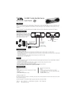
DRM12A Loudspeaker: Rear Panel Features ...................13
 

1. AC In Jack ...............................................................13


2. AC Thru Jack ..........................................................13


3. AC Thru Circuit Breaker .........................................13


4. XLR Input ................................................................14


5. XLR Output .............................................................14


6. LCD Display ............................................................14


7. Speaker Control Knob ............................................14


8 and 9. Dual-Angle Pole Cup ....................................14

DRM Control Dashboard™ ................................................15
 Main .............................................................................15
 

Array Mode..................................................................16

 Sub 

 ..............................................................................16


EQ Setup ......................................................................17

 Delay ............................................................................18
 Configuration ..............................................................19

Array Usage .......................................................................22
 

Floor Mounting ..........................................................22

Protection Circuitry ..........................................................23
 Limiting ......................................................................23
 

Overexcursion Protection .........................................23


Thermal Protection ...................................................23

AC Power ...........................................................................23
Care and Maintenance .....................................................23

Rigging   ............................................................................. 24
Room Acoustics ................................................................26

Appendix A: Service Information ..................................... 27
Appendix B: Technical Information .................................28
 

DRM12A Dimensions .................................................29


DRM12A Block Diagram ............................................30

Limited Warranty ...............................................................31

Summary of Contents for DRM12A

Page 1: ...OWNER S MANUAL 2000W 12 Arrayable Powered Loudspeaker DRM12A...

Page 2: ...ong 20 The AC Mains PowerCon connector the appliance coupler is used as the disconnect device This connector shall remain readily accessible and operable 21 The use of apparatus is in tropical and or...

Page 3: ...XLR Input and Output Premium components and cabinet design o Road worthy 15mm plywood construction and internal bracing offers optimal acoustic performance with a touring grade textured coating and p...

Page 4: ...gned so the transducers are positioned as close together as possible More specifically the separation between the transducers must be less than the wavelengths emitted by them This is easy to achieve...

Page 5: ...uts on the rear panel of the DRM12A loudspeakers 4 Push the line cord securely into the subwoofer s IEC connectors and plug the other ends into grounded AC outlets The subwoofer may accept the appropr...

Page 6: ...jack to the second DRM12A s input jack using a balanced XLR cable A short 1 2 foot cable is all that is necessary Hook up the supplied loop Neutrik PowerCon cable from the first DRM12A s AC Thru jack...

Page 7: ...vocal reinforcement Another possibility is to place DRM12As on the stage as front or side fills This helps provide sound to the fans near the stage where they may not be adequately covered by the PA T...

Page 8: ...gle position and the subwoofer HPF to DRM Sub Or set it to Var if not using the DRM18S It is possible to reproduce this exact same hookup in stereo for even wider and louder dispersion Simply utilize...

Page 9: ...he left and right main outputs from the mixer to feed the main inputs of the first DRM12A on each side of the stage and mirror the rest of the system as described above Another important aspect to kee...

Page 10: ...high frequencies in mono and the sub provides the low frequencies in mono Since three DRM12As are used the array mode should be set to the 3 4 or 3 4 long position and the subwoofer HPF to DRM Sub Or...

Page 11: ...e hookup in stereo Simply utilize the left and right main outputs from the mixer to feed the inputs of the top boxes and mirror the rest of the system as identified above Another important aspect to k...

Page 12: ...Top See pages 16 and 22 for more information It is possible to reproduce this exact same hookup in stereo Simply utilize the left and right main outputs from the mixer to feed the main inputs of the t...

Page 13: ...things turned off This will reduce the possibility of any turn on or turn off thumps in the loudspeakers 2 AC Thru Jack The Neutrik PowerCon AC IN and AC THRU connectors are wired in parallel to provi...

Page 14: ...OLD HOT SHIELD COLD HOT 3 2 1 INPUT OUTPUT PUSH FOR SETTINGS SPEAKER CONTROL 7 6 4 5 2 1 SHIELD COLD HOT 3 SHIELD COLD HOT 3 2 1 6 LCD Display This modern high resolution all color TFT LCD Display is...

Page 15: ...avigate between the selections and push the button to open and edit the parameters In 2 3 4 Long Array Mode DRM SUB Subwoofer 9 ms Delay 6 130 7 1 25k 10 15 5k Low Mid High Main EQ Array Delay Sub Con...

Page 16: ...mode is calculated to account for up to 100 feet of air loss compensation The top box in a flown three or four box array typically has to reach an audience that is much further away than those covered...

Page 17: ...s you to the menu SUBWOOFER HPF 90Hz VAR VAR OFF DRM SUB SUBWOOFER HPF 90Hz VAR VAR OFF DRM SUB EQ Setup On to the bottom row now The first one listed is EQ and as you might expect this is where to ad...

Page 18: ...setting up at shows by recalling previous settings The DRM12A s RTA fits right in with that literally displaying frequencies shortening the time it takes to tune the main loudspeakers or stage monito...

Page 19: ...RE 3 There are six user memory snapshots which should be more than enough Store Tap this to store the current settings to the corresponding memory snapshot Please be aware that the new settings will r...

Page 20: ...trol knob to select between on or off Like the previous sub menus configuration also has a left facing arrow Illuminating and selecting this simply returns you to the menu CONFIGURATION MEMORY 1 2 3 4...

Page 21: ...DSP versions temperature favorite movie and more There is really only one reason to go here and that is if you ve been directed so by Technical Support CONFIGURATION MEMORY 1 2 3 4 5 6 ABOUT LOCK PIN...

Page 22: ...e sure that the support surface e g floor etc has the necessary mechanical characteristics to support the weight of the loudspeaker s When pole mounting loudspeakers be sure that they are stabilized a...

Page 23: ...the thermal switch activates try turning down the level control a notch or two on the mixing console or via the Speaker Control knob to avoid overheating the amplifier Be aware that direct sunlight an...

Page 24: ...systems DRM12A Fly Points MP Mounting Point Rigging Hardware and Accessories Rigging a DRM12A will invariably require hardware not supplied by us Various types of load rated hardware are available fr...

Page 25: ...hookup diagrams to view additional rigging suggestions WARNING When the FB100 Flybar is used to suspend a system it cannot retain a 10 1 design factor at certain pick points In some situations suspen...

Page 26: ...sier than lower frequencies By providing direct line of sight from the loudspeakers to the audience you increase the overall brightness and intelligibility of the sound system Highly reverberant rooms...

Page 27: ...u think your DRM12A loudspeaker has a problem please check out the following troubleshooting tips and do your best to confirm the problem Visit the Support section of our website www mackie com suppor...

Page 28: ...on Display LEDs Defeatable front power Speaker Control Status Info Input and output levels array mode high pass filter EQ and delay settings AcousticPerformance Frequency Range 10 dB 50 Hz 20 kHz Freq...

Page 29: ...f supporting the weight of the DRM12A loudspeaker or fly via the integrated M10 mounting points using M10 x 1 5 x 20 mm forged shoulder eyebolts See page 22 24 26 for more information Options DRM12A C...

Page 30: ...le Powered Loudspeaker DRM12ALoudspeakerBlockDiagram HF x3 LF Amp Amp 4 User Selectable Array Modes User Adjustable Parametric EQ Alignment Delay Newton s Cradle Internal Crossover LF Equalization HF...

Page 31: ...liance within the Warranty Period to the Company at www mackie com or by calling LOUD technical support at 1 800 898 3211 toll free in the U S and Canada during normal business hours Pacific Time excl...

Page 32: ...16220 Wood Red Road NE Woodinville WA 98072 USA Phone 425 487 4333 Toll free 800 898 3211 Fax 425 487 4337 www mackie com...

Reviews: