background image

28

d.4 Pro DJ Production Console

d.

4 Pr

o 4-channel DJ Pr

oduc

tion C

ons

ole

MIDI notes

The d.4 Pro will show up on a Mac or PC as a 1 input, 

0 output MIDI interface named “D.Pro Mixer.” On a PC, 
the 0x1 MIDI interface shows up in all MIDI compatible 
applications. On a Mac, the 0x1 interface will show up 
in all compatible applications, and be visible in the  
Audio MIDI setup utility.

The single MIDI input will present, to any MIDI com-

patible application, the following MIDI messages:

•  A controller message, tied to the crossfader, 

with a value of 0 at hard left, 127 at hard right, 
with in-between values equally spread out 
across the crossfader’s travel. This allows you to 
use the crossfader as a performance controller 
with all sorts of audio software.

•  A separate, unique MIDI note-on message for 

each program fader that is assigned to the 
crossfader. The note-on message will be gener-
ated when the crossfader is moved even slightly 
from the side to which the program channel is 
assigned. This will allow you to trigger sound 
effects or musical passages from audio software 
that can respond to MIDI note-on messages. 
Similarly, the note-off message is generated 
when the crossfader reaches the end of its 
travel at the side where it is assigned. Each pro-
gram channel is assigned a note number that 
accompanies the note-on and note-off messag-
es. 0 is presented for channel 1, 1 for channel 2, 
2 for channel 3, and 3 for channel 4.

Software installation

For the PC:

When using the d.4 Pro with a PC, it is necessary to 

first install the drivers and the control panel. The con-
trol panel allows you to set the sample rate and adjust 
the latency (delay) of the audio passing through the d.4 
Pro FireWire interface.

Do not connect the d.4 Pro FireWire con-
nector to your computer just yet. 

We’ll tell 

you when it’s time to do that.

To install the software on a PC running 

Windows XP (SP2):

1.  Turn off any (non-essential) applications.
2.  Insert the d.4 Pro CD-ROM into your PC’s CD-

ROM drive.

3. Click Start in the task bar, then click Run and 

click Browse. Browse to your CD drive and 
double-click d.Pro_SETUP.EXE. Then click OK 
to start the installation.

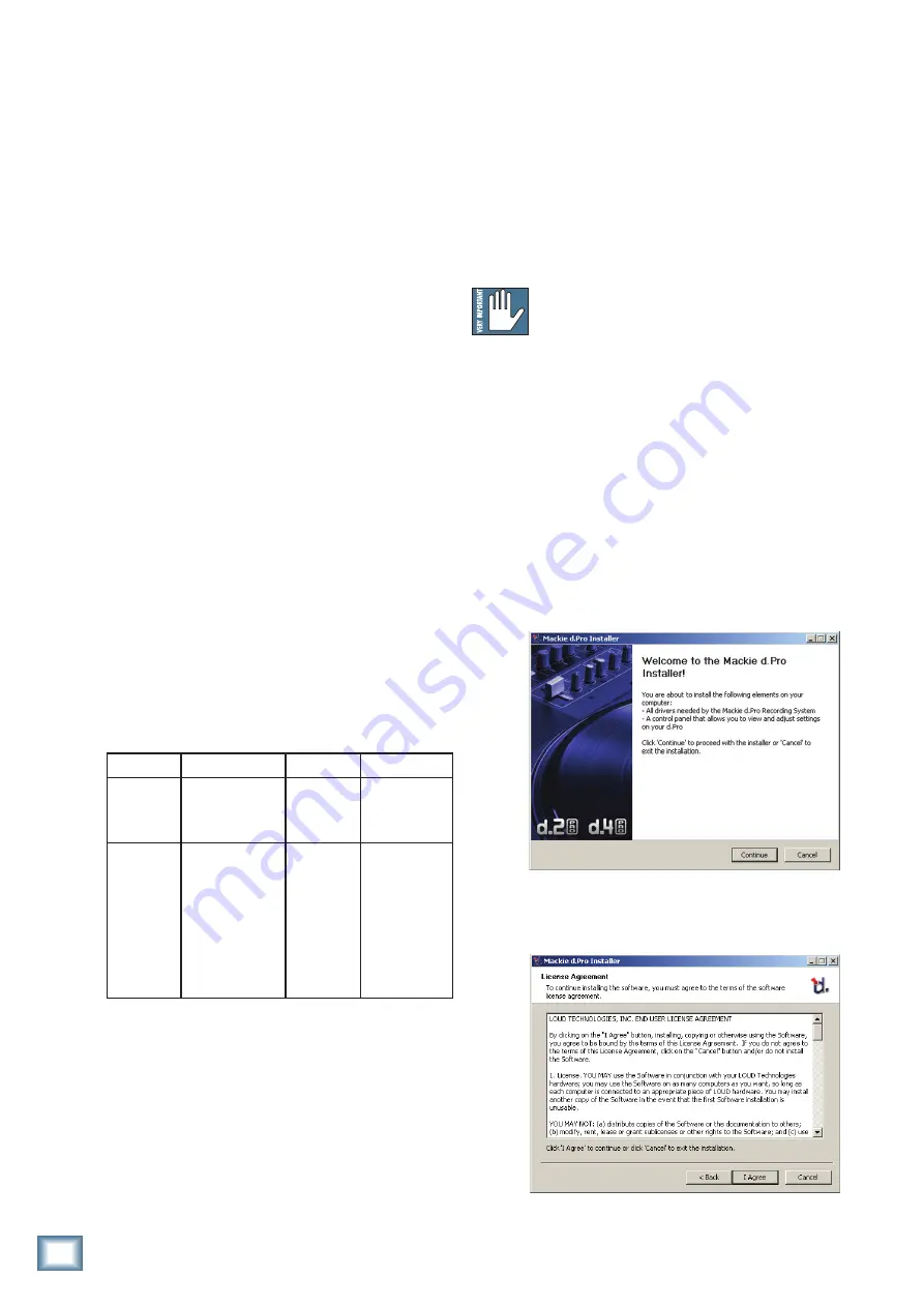
4.  The d.Pro Installer opens. Click “Continue.”

5.  Next you will see the License Agreement. Read 

through the text and if you are all in favor, click 
“I Agree.”

Action

Status

Data 1

Data 2

Crossfader 
position

Value: 176
Control Change
Channel 1

Value: 4
Foot
Controller

Value: 0 to 127
Crossfader 
position

Note on/ 
Note off
for PGM 
channels 
assigned 
to the 
crossfader 
(A or B)

Value: 144
Note on, Ch 1

Value: 0, 1, 
2, or 3
PGM Ch 
number
PGM ch 1: 0
PGM ch 2: 1
PGM ch 3: 2
PGM ch 4: 3

Value: 0 to 127
Note on: 127
Note off: 0

Summary of Contents for d.4 Pro

Page 1: ...OWNER S MANUAL 4 Channel DJ Production Console with FireWire CUE CUE CUE CUE...

Page 2: ...he user is encouraged to try to correct the interference by one or more of the following measures Reorient or relocate the receiving antenna Increase the separation between the equipment and the recei...

Page 3: ...S 13 22 48V LED 13 23 HIGH EQ 13 24 MID EQ 13 25 LOW EQ 13 26 AUX 13 27 MAIN 13 28 MIC ASSIGN 14 PROGRAM CHANNEL SECTION 14 29 LEVEL 14 30 SOURCE 14 31 HIGH EQ 14 32 MID EQ 14 33 LOW EQ 14 34 FILTER S...

Page 4: ...th live record switch The record position delivers a pre fader main out User replaceable optical crossfader from Infinium with adjustable tension and contour Ultra bright main meters plus individual p...

Page 5: ...manufacturer recommends This is usually all the way up Set the Levels To set the level controls it s not even necessary to hear what you re doing at the outputs of the mixer To listen while you work...

Page 6: ...1 Powered Subwoofer SWA1501 Powered Subwoofer SRM450 Powered Speaker Main Left Main Left Main Right SRM450 Powered Speaker Main Right This diagram shows a CD player and microphones connected with an e...

Page 7: ...ce switch each program can quickly select from three different inputs without repatching FireWire Line or Phono set Line Phono switch CD Player or other line level The output from various software suc...

Page 8: ...p CD Recorder HR824 Powered Studio Monitors Turntable PGM4 with phono level output This diagram shows a keyboard drum machine turntable and CD turntable with two microphones A USB keyboard controller...

Page 9: ...ntable PGM 4 CD Turntable PGM 3 Laptop Computer Main Left Main Right Turntables with phono level outputs Effects Processor out in Microphones This diagram shows 4 sources hooked up to 4 channels with...

Page 10: ...whether your microphone needs phan tom power or not 3 CDInputs The bottom pair of RCA jacks accept a stereo line lev el signal from a CD player or other line level playback device such as an MP3 playe...

Page 11: ...puts These 1 4 TRS jacks provide a balanced line level signal from the main mix bus prior to the rotary main level control 55 or pan 56 Use these to connect to a pair of powered monitors in the booth...

Page 12: ...Pro has a universal power supply that accepts any AC voltage from 100 VAC to 240 VAC It will work vir tually anywhere in the world It is less susceptible than conventional power supplies to voltage s...

Page 13: ...e center position U unity gain there is no effect on the signal If all three EQ controls are set to minimum the mic signals are attenuated 15 dB across the audio range 24 MIDEQ These knobs give your m...

Page 14: ...to 10 dB of boost at 4 kHz and above and turns off the signal at 4 kHz and above when the knob is turned to the kill position At the center position U there is no effect on the signal Note When all t...

Page 15: ...d using the aux send 40 control and sent out to FireWire and the aux send 8 TRS outputs typically to an external effects processor The aux signals are affected by the settings of the program source 30...

Page 16: ...ltage to a pair of VCAs that deter mine the gain of the signal This is a very good thing by the way as the audio will not be affected by any scratchy electrical contacts 39 PROGRAMLEVELMETERS These me...

Page 17: ...remove the AC power cord 2 Move the crossfader all the way to the left 3 Remove the fader cap knob by grasping it firmly and pulling it straight up 4 Use a small slot head screwdriver to turn the scre...

Page 18: ...ange of the knob is off to 12 dB WARNING The headphone amp has enough gain to drive any standard headphones to a very loud level We re not kidding It can cause permanent hearing damage Even intermedia...

Page 19: ...record 15 switch is out This control does not affect the main meters 57 or the phones 51 booth 10 or zone 11 outputs or FireWire outputs 57 MAINLEVELMETERS These meters indicate the signal strength o...

Page 20: ...ou are certain that the AC outlet is live it will be necessary to have your d 4 Pro serviced There are no user serviceable parts inside Refer to Repair on the next page to find out how to proceed Appe...

Page 21: ...s come directly after the phono section In this way you can have the timecode flowing to your computer and use the source selector switch to play the computer output in that same program channel Repai...

Page 22: ...alanced signals and stereo headphones BalancedMono SLEEVE TIP SLEEVE TIP RING RING TIP SLEEVE RING 1 4 TRS Balanced Mono Wiring Sleeve Shield Tip Hot Ring Cold StereoHeadphones SLEEVE TIP SLEEVE TIP R...

Page 23: ...nputs preamp gain 0 dB 22 5 dBu Aux input 22 5 dBu Phono input 185 mV 1kHz Input Output Characteristics Input gain control range Mic input 0 to 60 dB PGM input Off to 12 dB Aux return Off to 12 dB Out...

Page 24: ...GHT BUS FILTER X CUE ON FILT X wet L R dry wet Wet 100 to Aux 0 to Main Mix Dry 0 to Aux 100 to Main Mix Wet 100 to Aux 0 to Main Mix Dry 0 to Aux 100 to Main Mix dry PGRM FILT Y OFF BUMP HP BP LP OFF...

Page 25: ...n a flat clean and dry surface such as the kitchen table 3 Remove the crossfader knob by gently pulling it upwards Keep it safe 4 Take care to only remove the two outer screws of the crossfader 5 Gent...

Page 26: ...t 8 PGM 4 R Line Phono or Post EQ Input 9 MIC 1 Input 10 MIC 2 Input 11 AUX Send L Input 12 AUX Send R Input 13 MAIN Out L Input 14 MAIN Out R FireWirestreamtocomputer The following table shows the ou...

Page 27: ...a care in the world With the source selector set to FireWire you can now bring in the affected audio from your virtual turntable and play it through the same program channel and onto the main mix bus...

Page 28: ...e side where it is assigned Each pro gram channel is assigned a note number that accompanies the note on and note off messag es 0 is presented for channel 1 1 for channel 2 2 for channel 3 and 3 for c...

Page 29: ...en click Next 9 Wait until the Found New Hardware Wizard pops up Do not select any options just click Cancel to continue If the same screen comes back up click Cancel again 10 You will get another imp...

Page 30: ...require FireWire drivers to be installed OS X provides a dedicated setup utility for audio and MIDI You can use the Audio MIDI Setup utility to change the default audio input and output and general sy...

Page 31: ...for those units deemed by us to be under warranty Note You must have a sales receipt from an authorized Mackie dealer for your unit to be considered for warranty repair IMPORTANT Make sure that the Se...

Page 32: ...Road NE Woodinville WA 98072 USA United States and Canada 800 898 3211 Europe Asia Central and South America 425 487 4333 Middle East and Africa 31 20 654 4000 Fax 425 487 4337 www mackie com E mail s...

Reviews: