


22
OPERATION MANUAL
F
ig
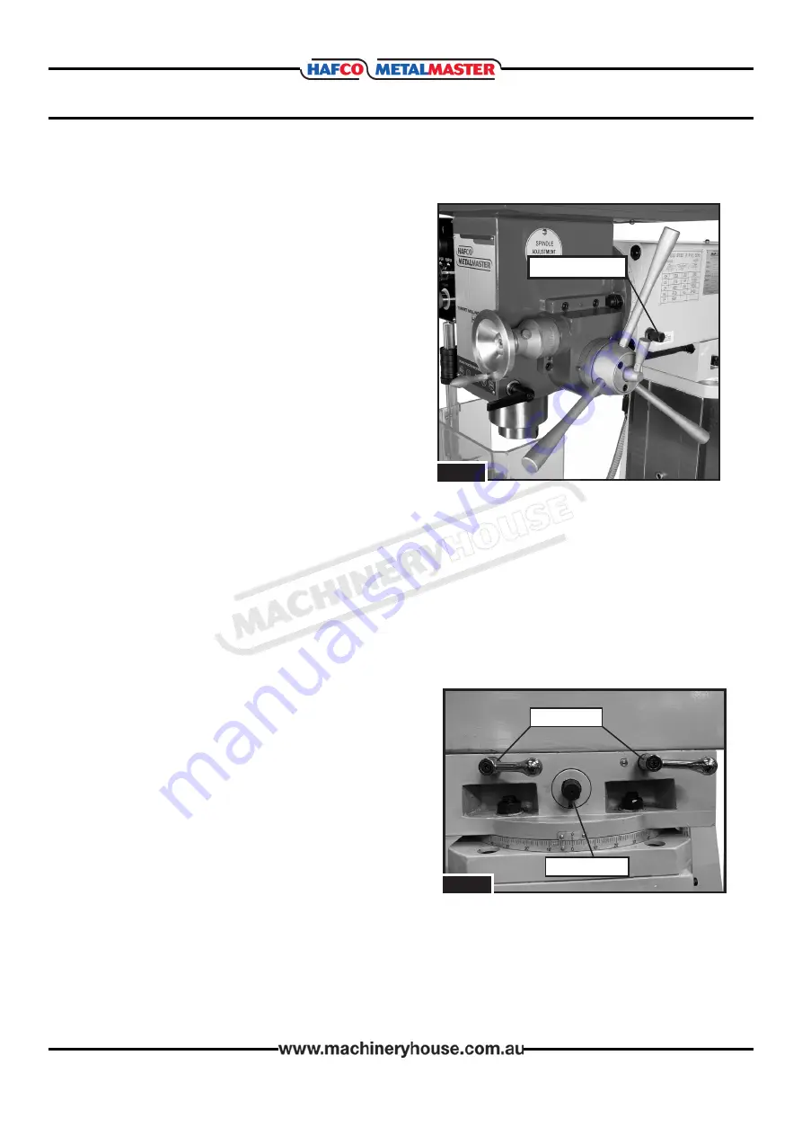
. 5.6
3. It then will be possible to tilt the head down
to the required position, by slowly turning the
hexagon worm pinion shaft on the right hand
side behind the spindle, (Fig.5.6) either clock
wise or anticlockwise.
4. When the correct angle of the head is obtained
ensure the 3 x hexagon nuts located at the
head end of the over arm are firmly
re-tightened.
Note
: Use the angle scale shown in Fig. 5.5 as a
guide for setting tilt angle. For an accurate angle
the use of a protractor will be required.
w
orM
pinion
sHaFt
NOTE:
Because of the Mill heads heavy overhung weight. It is strongly recommended that
when returning the mill head of the machine back up to any position. That, while the hexagon
worm pinion shaft on the right hand side of the over arm is turned. A second person should
give assistance to push the head back up as needed. Always ensure the 3 x hexagon nuts
located at the head end of the over arm are firmly re-tightened after every move.
RAM MOVEMENT
F
ig
. 5.7
l
ocK
Handles
p
inion
gear
Bolt
The ram travels forward/backward 300mm and
rotates 180° on the turret.
Moving Ram Forward/Backward
1. DISCONNECT THE MACHINE FROM POWER!
2. Loosen the two lock handles shown in Fig.5.7
3. Rotate pinion gear bolt to move ram until
spindle is in desired position.
4. Retighten lock handles to secure ram movement
before resuming operation.
08/11/2019
Instructions Manual for HM-54GV (M579)
22


