Page 30
Care must be taken when transporting the machine due to the minimal clearance between
the output connector of the pump and the ground. As the unit is “pushed” the pump
connector is the furthermost pint of the machine and thus prone to damage from impact
with objects in front of the machine or from the ground itself. The machine must be
“eased” up curbs or steps.
Once the machine has been positioned then the locks on the rear swivel casters should be
set.
Pay consideration to water source, power and material locations when setting the
machine in position. The site must be flat and level to ensure that the machine operates
from a horizontal position.
Summary of Contents for MP-25
Page 6: ...Page 6 Machine illustrations Photographs Single phase STD output unit shown...
Page 7: ...Page 7 Illustration 60010120 ASSY MP 25 SO SINGLE PHASE 220V...
Page 8: ...Page 8 Bill of Materials 60010120 ASSY MP 25 SO SINGLE PHASE 220V...
Page 9: ...Page 9 Illustration 60010121 ASSY MP 25 HO 3 PHASE 220V...
Page 10: ...Page 10 Bill of Materials 60010121 ASSY MP 25 HO 3 PHASE 220V...
Page 14: ...Page 14 Water plate assemblies 60010136 ASSY WATER CONTROL MP 25 4GPM...
Page 15: ...Page 15 60010142 ASSY WATER CONTROL MP 25 7GPM...
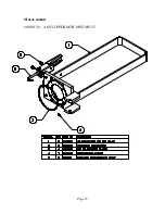
Page 16: ...Page 16 Motor mount 60010134 ASSY UPPER MTR MNT MP 25...
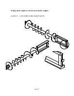
Page 17: ...Page 17 Mixing shaft complete and clean out shaft complete 60010125 ASSY DRIVE MIX SHAFT MP 25...
Page 18: ...Page 18 60010126 ASSY SHAFT CLEAN OUT MP 25...
Page 20: ...Page 20 60010147 ASSY PUMP HOSE COMPLETE MP 25...
Page 21: ...Page 21 60010144 ASSY FAN DUCT MP 25 60010148 ASSY WASHDOWN HOSE COMPLETE MP 25...
Page 26: ...Page 26 Illustrations 20000046 3 phase...
Page 27: ...Page 27 20000047 single phase...
Page 28: ...Page 28 With cowl...


