background image

i-

ALERT® Gateway Installation Guide


5/13 

2


System View 

2.1


Gateway Interface 

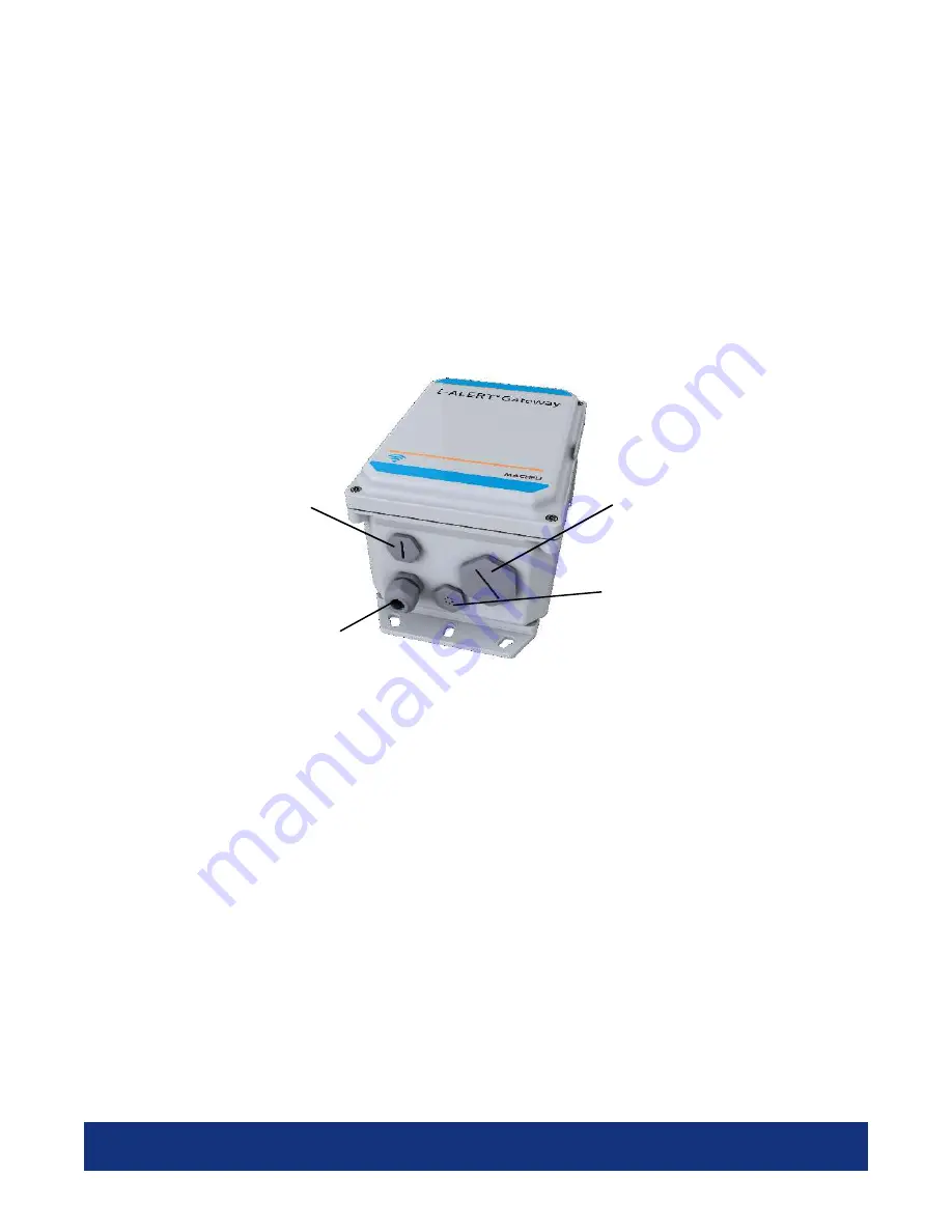
The gateway interface points are shown in Figure 1: 

1.


Plug 1 is an expansion plug allowing an additional gland or conduit fitting to be added 

2.


Plug 2 is the gland for the power input cable 

3.


Plug 3 is a water tight air exchange vent 

4.


Plug 4 is the Cellular SIM card access plug 


Figure 1: i-ALERT2® Gateway Interface Ports 


4. SIM Card 

3. IP67/IP68 Rated 
Air Vent 

3. IP67/IP68 Rated 
Hole Plug 

3. IP67/IP68 Rated 
Gland 

Summary of Contents for i-ALERT Series

Page 1: ...i ALERT Gateway Installation Manual August 8 2019 Revision 2 0 ...

Page 2: ...indicates important information that helps you make better use of your product CAUTION A CAUTION indicates either potential damage to hardware or loss of data and tells you how to avoid the problem WARNING A WARNING indicates a potential for property damage personal injury or death ...

Page 3: ...ce 5 2 2 Powering the Gateway 6 2 2 1 AC Powered Gateway 6 2 2 2 9 60 VDC Powered Gateway 6 2 2 3 Conduit Fittings 7 2 3 Mounting Options 8 2 3 1 Wall Mounting 8 2 3 2 Pole Mounting 9 3 i ALERT Gateway Quick Start Guide 10 3 1 Troubleshooting 11 4 Safety and regulatory information 12 5 Regulatory Notices 12 ...

Page 4: ...i ALERT Gateway Installation Guide 3 13 REVISION HISTORY Revision Description Date 0 1 Draft release 4 4 2019 1 0 Draft revision 5 10 2019 2 0 Draft revision 6 30 2019 3 0 Final Revision 8 8 2019 ...

Page 5: ...n both a North American and International versions Part Numbers are as follows Model Part Number Description i ALERT Gateway Domestic AC Powered USA K13653A US 110 240 VAC Domestic Cellular Modem Assembly USA i ALERT Gateway Domestic AC Powered CD K13653A CD 110 240 VAC Domestic Cellular Modem Assembly Canada i ALERT Gateway Domestic DC Powered USA K13654A US 9 60 VDC Domestic Cellular Modem Assem...

Page 6: ...expansion plug allowing an additional gland or conduit fitting to be added 2 Plug 2 is the gland for the power input cable 3 Plug 3 is a water tight air exchange vent 4 Plug 4 is the Cellular SIM card access plug Figure 1 i ALERT2 Gateway Interface Ports 4 SIM Card 3 IP67 IP68 Rated Air Vent 3 IP67 IP68 Rated Hole Plug 3 IP67 IP68 Rated Gland ...

Page 7: ...he installation location when powering by this method Once wired and powered into a 110 VAC 240 VAC outlet or hardwired it will discover and begin communicating with all i ALERT2 sensors and posting data to the ITT AI Platform Figure 2 i ALERT2 120VAC 24VAC option 2 2 2 9 60 VDC Powered Gateway The gateway can be optionally ordered to be powered from 9 60VDC When powered in this way the unit is wi...

Page 8: ...replaced by a standard 20mm or conduit fitting See 4 WARNING If the i ALERT2 Gateway is rewired using conduit it must be installed by knowledgeable skilled personnel familiar with local and or international electrical codes and regulations Figure 4 Replacement of gland with a conduit fitting ...

Page 9: ...r is attached with two flat head screws item 5 Figure 6 provides information on the mounting hole pattern The gateway should be mounted vertically as shown in Figure 8 Item Description Qty 1 IP68 Enclosure 1 2 IP68 Cover 1 3 Cover Screws 4 4 Mounting Ears 2 5 Mounting Ear Screws 4 7 Air Vent 1 8 Blank Plug 1 9 SIM Plug 1 10 Power Cable Gland 1 Figure 6 Gateway Back plate Mounting Diagram Figure 5 ...

Page 10: ...wn in Figure The pole mount kit can be used with poles of diameter of 2 inches to 12 inches To mount the bracket to the gateway remove the mounting ears by removing the screws 4 X item 5 Figure Then attach the brackets using the four screws item 6 and washers item 7 as shown in Figure Figure 7 Pole Mount Bracket Kit Figure 8 Gateway with pole mount bracket ...

Page 11: ...minimum of 6 ft 2m off the ground and no more than 50ft 15m above any i ALERT enabled machines Verify the i ALERT gateway environmental and hazardous location ratings meet the minimum requirements for the area selected Power Up The i ALERT Gateway comes in two versions A 120 220VAC and a 9 60VDC version Check the label on the bottom of the gateway to determine which voltage to apply Install power ...

Page 12: ...ke sure you are looking at the correct account If you are not sure who the sensors is registered to and need assistance contact us at support i alert ai with a picture of i ALERT sensor serial number located on the bottom of the i ALERT sensor How do I know the i ALERT Gateway is communicating properly With a personal computer or mobile device make sure you are in wireless range of the gateway Go ...

Page 13: ... i ALERT2 Gateway is reliably grounded and filtered such that the peak to peak ripple component is less than 10 percent of the input DC voltage WARNING To ensure the protection provided by the i ALERT2 Gateway is not impaired do not use or install the system in any manner other than what is specified in this manual 5 Regulatory Notices FCC Statement This equipment has been tested and found to comp...

Page 14: ...e aux CNR d Industrie Canada applicables aux appareils radio exempts de licence L exploitation est autorisée aux deux conditions suivantes 1 l appareil ne doit pas produire de brouillage 2 l utilisateur de l appareil doit accepter tout brouillage radioélectrique subi même si le brouillage est susceptible d en compromettre le fonctionnement This transmitter must not be co located or operated in con...

Reviews: