background image

4

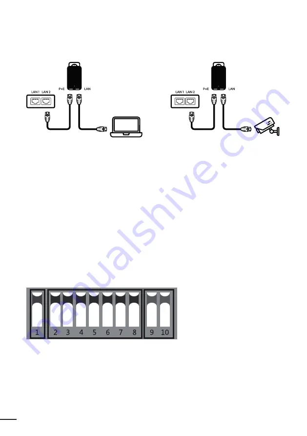
1. CONNECTION DIAGRAM

1.1 

Connection diagram between POE with the CPE 

POE port: 

connect the LAN1 or LAN2 port to the AP.

LAN POE:

 connect to PC, camera, Switch or XVR.

Notes
1. 

Both RJ45 ports (black and yellow) on the AP are LAN connections.

2. 

If you want to enter the web page, you have to manually enter the IP address of the PC.

3. 

The POE adapter has 3 inputs. One for the power cable, 2 for connectivity.

4. 

The POE adapter is not intended for outdoor use. It is advisable to keep it away from atmospheric 

phenomena.

At the bottom of the device there are 2 RJ45 inputs, one called POE and the other LAN.
Use a Cat5 cable to connect the device to the PC, camera, Switch or XVR.

2. DIP DEVICE INSTRUCTION

Key 1:

 changes the device mode, UP is the AP (Access Point) mode to be used for PC, Switch or XVR, 

DOWN to be used for cameras.

Keys 2 to 8:

 these are for the coupling of different AP devices. There are 128 different combinations 

that can be created using the 7 Matching keys, which correspond to 128 different SSIDs and 128 diffe-
rent segments. Pages 8 to 15 below show all possible combinations.

Summary of Contents for WL-CPE2G24D-075

Page 1: ...User manual CPE DIP SWITCH POE 24V WL CPE2G24D 075 WL CPE5G24D 076 WL CPE5G24D 080...

Page 2: ......

Page 3: ...ENG INDEX 1 Connection Diagram 1 1 Connection diagram between POE with the CPE 2 DIP Device instruction 3 Setting the signal strength 4 Questions answers 5 DIP codes segment and frequency 4 4 4 6 7 9...

Page 4: ...utdoor use It is advisable to keep it away from atmospheric phenomena At the bottom of the device there are 2 RJ45 inputs one called POE and the other LAN Use a Cat5 cable to connect the device to the...

Page 5: ...9 raised and 10 raised 3 Switch settings between cameras cannot be duplicated for buttons 9 and 10 or interference may be caused up to 4 points Remarks 1 Restart the AP after finishing the DIP setting...

Page 6: ...55 0 0 Ip address for 5 8G devices is 172 18 0 2 Subnet Mask is 255 255 0 0 Enter the IP address of the corresponding AP device in the IE browser to enter the WEB page the default password is password...

Page 7: ...d turn on the device and wait 3 minutes The distance between the transmitter and the receiver must be more than 2 meters If you still see no indication that the units are on and communicating with eac...

Page 8: ...ss signal strength First LED lit very weak signal First and second LEDs lit weak signal First second and third LEDs on good signal All 4 LEDs lit optimal signal If only the last fourth LED is lit the...

Page 9: ...18 5 X 5745 172 17 5 X 2437 n 7 172 18 6 X 5765 172 17 6 X 2442 n 8 172 18 7 X 5785 172 17 7 X 2447 n 9 172 18 8 X 5805 172 17 8 X 2452 n 10 172 18 9 X 5825 172 17 9 X 2457 n 11 172 18 10 X 5160 172 1...

Page 10: ...432 n 28 172 18 27 X 5785 172 17 27 X 2437 n 29 172 18 28 X 5805 172 17 28 X 2442 n 30 172 18 29 X 5825 172 17 29 X 2447 n 31 172 18 30 X 5160 172 17 30 X 2452 n 32 172 18 31 X 5180 172 17 31 X 2457 n...

Page 11: ...2427 n 49 172 18 48 X 5805 172 17 48 X 2432 n 50 172 18 49 X 5825 172 17 49 X 2437 n 51 172 18 50 X 5160 172 17 50 X 2442 n 52 172 18 51 X 5180 172 17 51 X 2447 n 53 172 18 52 X 5200 172 17 52 X 2452...

Page 12: ...422 n 70 172 18 69 X 5825 172 17 69 X 2427 n 71 172 18 70 X 5160 172 17 70 X 2432 n 72 172 18 71 X 5180 172 17 71 X 2437 n 73 172 18 72 X 5200 172 17 72 X 2442 n 74 172 18 73 X 5220 172 17 73 X 2447 n...

Page 13: ...n 91 172 18 90 X 5160 172 17 90 X 2422 n 92 172 18 91 X 5180 172 17 91 X 2427 n 93 172 18 92 X 5200 172 17 92 X 2432 n 94 172 18 93 X 5220 172 17 93 X 2437 n 95 172 18 94 X 5240 172 17 94 X 2442 n 96...

Page 14: ...12 172 18 111 X 5180 172 17 111 X 2417 n 113 172 18 112 X 5200 172 17 112 X 2422 n 114 172 18 113 X 5220 172 17 113 X 2427 n 115 172 18 114 X 5240 172 17 114 X 2432 n 116 172 18 115 X 5745 172 17 115...

Page 15: ...15 ENG n 125 172 18 124 X 5240 172 17 124 X 2427 n 126 172 18 125 X 5745 172 17 125 X 2432 n 127 172 18 126 X 5765 172 17 126 X 2437 n 128 172 18 127 X 5785 172 17 127 X 2442...

Page 16: ......

Page 17: ...1 Diagramma di connssione 1 1 Schema di connessione tra POE con la CPE 2 Istruzioni dispositivo DIP 3 Impostazione della potenza del segnale 4 Domande Risposte 5 Codici DIP segmenti e frequenze 18 18...

Page 18: ...erlo al riparo dai feno meni atmo sferici Nella parte inferiore del dispositivo sono presenti 2 ingressi RJ45 uno denominato POE e l altro LAN Usare un cavo Cat5 per collegare il dispositivo al PC tel...

Page 19: ...3 Non possibile duplicare le impostazioni di commutazione tra le telecamere per i tasti 9 e 10 o si potrebbero causare delle interferenze per un massimo di 4 punti Osservazioni 1 Riavviare l AP dopo...

Page 20: ...172 18 0 2 Subnet Mask 255 255 0 0 Digitare l indirizzo IP del dispositivo AP corrispondente nel browser IE per accedere alla pagina WEB la password predefinita password La potenza del segnale pu esse...

Page 21: ...dispositivo e attendere 3 minuti La distanza tra il trasmettitore e il ricevente deve essere superiore ai 2 metri Se ancora non si vede alcuna indicazione che le unit sono accese e comunicano tra loro...

Page 22: ...LED accesi segnale debole Primo secondo e terzo LED accesi segnale buono Tutti e 4 LED accesi segnale ottimale Se acceso solo L ultimo LED quarto il segnale troppo forte Provare a impostare la potenz...

Page 23: ...ent 2 4GHz n 1 172 18 0 X 5160 172 17 0 X 2412 n 2 172 18 1 X 5180 172 17 1 X 2417 n 3 172 18 2 X 5200 172 17 2 X 2422 n 4 172 18 3 X 5220 172 17 3 X 2427 n 5 172 18 4 X 5240 172 17 4 X 2432 n 6 172 1...

Page 24: ...37 n 18 172 18 17 X 5785 172 17 17 X 2442 n 19 172 18 18 X 5805 172 17 18 X 2447 n 20 172 18 19 X 5825 172 17 19 X 2452 n 21 172 18 20 X 5160 172 17 20 X 2457 n 22 172 18 21 X 5180 172 17 21 X 2462 n...

Page 25: ...2432 n 39 172 18 38 X 5805 172 17 38 X 2437 n 40 172 18 39 X 5825 172 17 39 X 2442 n 41 172 18 40 X 5160 172 17 40 X 2447 n 42 172 18 41 X 5180 172 17 41 X 2452 n 43 172 18 42 X 5200 172 17 42 X 2457...

Page 26: ...427 n 60 172 18 59 X 5825 172 17 59 X 2432 n 61 172 18 60 X 5160 172 17 60 X 2437 n 62 172 18 61 X 5180 172 17 61 X 2442 n 63 172 18 62 X 5200 172 17 62 X 2447 n 64 172 18 63 X 5220 172 17 63 X 2452 n...

Page 27: ...2422 n 81 172 18 80 X 5160 172 17 80 X 2427 n 82 172 18 81 X 5180 172 17 81 X 2432 n 83 172 18 82 X 5200 172 17 82 X 2437 n 84 172 18 83 X 5220 172 17 83 X 2442 n 85 172 18 84 X 5240 172 17 84 X 2447...

Page 28: ...101 X 5180 172 17 101 X 2422 n 103 172 18 102 X 5200 172 17 102 X 2427 n 104 172 18 103 X 5220 172 17 103 X 2432 n 105 172 18 104 X 5240 172 17 104 X 2437 n 106 172 18 105 X 5745 172 17 105 X 2442 n 1...

Page 29: ...5 172 17 118 X 2452 n 120 172 18 119 X 5825 172 17 119 X 2457 n 121 172 18 120 X 5160 172 17 120 X 2462 n 122 172 18 121 X 5180 172 17 121 X 2412 n 123 172 18 122 X 5200 172 17 122 X 2417 n 124 172 18...

Page 30: ...30...

Page 31: ...agrama de conexi n 1 1 Diagrama de conexi n entre POE con el CPE 2 Instrucciones del dispositivo DIP 3 Configurar la fuerza de la se al 4 Preguntas y respuestas 5 C digos DIP segmentos y frecuencias 3...

Page 32: ...tenerlo alejado de los fen menos atmosf ricos En la parte inferior del dispositivo hay 2 entradas RJ45 una llamada POE y la otra LAN Utilice un cable Cat5 para conectar el dispositivo a la PC c mara S...

Page 33: ...y 10 levantada 3 Los ajustes de cambio entre c maras no se pueden duplicar para los botones 9 y 10 o pueden pro ducirse interferencias hasta 4 puntos Observaciones 1 Reinicie el AP despu s de finaliz...

Page 34: ...0 2 La m scara de subred es 255 255 0 0 Ingrese la direcci n IP del dispositivo AP correspondiente en el navegador IE para ingresar a la p gina WEB la contrase a predeterminada es password La intensi...

Page 35: ...or lo recibido re ajuste los botones 1 ABAJO y botones 2 a 10 ARRIBA Al final encienda el dispositivo y espere 3 minutos La distancia entre el transmisor y el receptor debe ser superior a 2 metros Si...

Page 36: ...o Naranja intensidad de la se al inal mbrica Primer LED encendido se al muy d bil Primer y segundo LED encendidos se al d bil Primer segundo y tercer LED encendidos buena se al Los 4 LED encendidos se...

Page 37: ...2 18 5 X 5745 172 17 5 X 2437 n 7 172 18 6 X 5765 172 17 6 X 2442 n 8 172 18 7 X 5785 172 17 7 X 2447 n 9 172 18 8 X 5805 172 17 8 X 2452 n 10 172 18 9 X 5825 172 17 9 X 2457 n 11 172 18 10 X 5160 172...

Page 38: ...432 n 28 172 18 27 X 5785 172 17 27 X 2437 n 29 172 18 28 X 5805 172 17 28 X 2442 n 30 172 18 29 X 5825 172 17 29 X 2447 n 31 172 18 30 X 5160 172 17 30 X 2452 n 32 172 18 31 X 5180 172 17 31 X 2457 n...

Page 39: ...2427 n 49 172 18 48 X 5805 172 17 48 X 2432 n 50 172 18 49 X 5825 172 17 49 X 2437 n 51 172 18 50 X 5160 172 17 50 X 2442 n 52 172 18 51 X 5180 172 17 51 X 2447 n 53 172 18 52 X 5200 172 17 52 X 2452...

Page 40: ...422 n 70 172 18 69 X 5825 172 17 69 X 2427 n 71 172 18 70 X 5160 172 17 70 X 2432 n 72 172 18 71 X 5180 172 17 71 X 2437 n 73 172 18 72 X 5200 172 17 72 X 2442 n 74 172 18 73 X 5220 172 17 73 X 2447 n...

Page 41: ...n 91 172 18 90 X 5160 172 17 90 X 2422 n 92 172 18 91 X 5180 172 17 91 X 2427 n 93 172 18 92 X 5200 172 17 92 X 2432 n 94 172 18 93 X 5220 172 17 93 X 2437 n 95 172 18 94 X 5240 172 17 94 X 2442 n 96...

Page 42: ...12 172 18 111 X 5180 172 17 111 X 2417 n 113 172 18 112 X 5200 172 17 112 X 2422 n 114 172 18 113 X 5220 172 17 113 X 2427 n 115 172 18 114 X 5240 172 17 114 X 2432 n 116 172 18 115 X 5745 172 17 115...

Page 43: ...43 ES n 125 172 18 124 X 5240 172 17 124 X 2427 n 126 172 18 125 X 5745 172 17 125 X 2432 n 127 172 18 126 X 5765 172 17 126 X 2437 n 128 172 18 127 X 5785 172 17 127 X 2442...

Page 44: ...For any information and product updates visit our website www machpower it Mach Power is a registered trademark All rights reserved REV01 060521...

Reviews: