background image

24    Draper Clinic Handout

 - FD1 FlexDraper

®

Performance Options

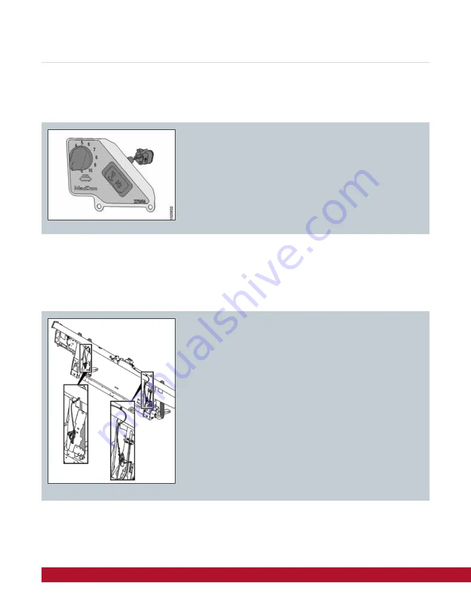
This option allows the operator the ability to adjust the speed of the side 
drapers from in the cab of the combine.

The kit contains a PWM valve that is installed into the hydraulic manifold 
and a wire harness that runs into the cab.  A suction mounted control 
panel contains the operator interface.

MD #B6387

This option provides additional auto header height control sensor 
inputs for the combine lateral tilt circuit allowing the FM100 Float 
Module to automatically pivot from side to side to follow uneven 
terrain during operation.

The combine requires feeder faceplate tilt option.

The kit adds two additional sensors to the float linkage.

Not compatible with New Holland 10 volt AHHC system. 

Not recommended for use on steep hills.

MD #B6211

In Cab Draper Speed Control

Dual Auto Header Height

Summary of Contents for FlexDraper FD1 Series

Page 1: ...Draper Clinic Handout FD1 FlexDraper...

Page 2: ...ce Lubrication Specs Chart 9 Maintenance 10 25 Hours 10 Maintenance 50 Hours 11 Maintenance 100 Hours 12 Maintenance 250 Hours 14 Maintenance 500 Hours 15 Maintenance 1000 Hours or 3 Years 16 End of S...

Page 3: ...ways Unlock Float when operating in the field Handle position A is locked for transport Rotate handle to position B for field operation 2 latches one on either side of Float Module Always Lock Flex fo...

Page 4: ...4 Hydraulics in the Operators Manual for more information Checkhydraulicoillevelinreservoir checkafterfirstrun upandafterhoseshavefilledwithoil Checkforloosehardwareandtightentorequiredtorque Checkkni...

Page 5: ...t is required If the difference B is greater than 8 mm 5 16 in the auger drive chain tension needs adjusting If the difference B is less than 3 mm 1 8 in the auger drive chain needs adjusting Refer to...

Page 6: ...4 turn by hand Confirm oil level in the reservoir and add as required Refer to Section 5 4 Hydraulics in the Operators Manual for more information Remove the oil drain plug A and the filler plug C and...

Page 7: ...ning the chainshouldhave 10 14mm 3 8 9 16in of deflectionat itsmidpoint Refer to Section 5 6 Header Drive in the Operators Manual for more information Checkheaderdrivegearboxchaintension Table5 1Adjus...

Page 8: ...de loosen tension on side draper grab draper at connector slat and lift up and rearward to remove draper from under cutterbar and expose the deck support Prop draper up with bar Measure and note the t...

Page 9: ...performance with 10 max Molybdenum Disulphide NLGI Grade 2 lithium base Driveline slip joints Gear Lubricant SAE 85W 140 API service class GL 5 Knife drive box 2 2liters 2 3quarts Main drive gearbox 2...

Page 10: ...ance is 0 1 0 6 mm 0 004 0 024 in Checking knife hold downs daily will keep your knife performing at peak levels prevent premature wear and ensure a longer life of all your cutting components ultimate...

Page 11: ...1 50 Hours A Drive roller bearing C Driveline Slip Joint A Upper Cross Auger U joint and Bearing Upper Cross Auger Bearing two places OptionalAttachment A C C D A B B B D B Idler roller bearing both s...

Page 12: ...C Driveline guard D Reel Drive Chain Refer to Section 5 12 Header Side Drapers in the Operators Manual for more information Checksidedraperdeckheightadjustment NOTE Correctlysettingsidedraperdeckheig...

Page 13: ...1 FlexDraper 13 A Knife Drive Box check oil level B on dipstick C Between lower hole D on dipstick and dipstick bottom edge E A Auger Pivots F UpperCrossAugerBearing OptionalAttachment oneplace G Main...

Page 14: ...ame Wheel Pivot Front and Rear both Sides B Front Wheel Pivot one Place B Flex Linkage two places Both sides A B OptionalAttachment NOTE Changefloatmodulehydraulicoilfilter refer to page 6 Changefloat...

Page 15: ...Draper Clinic Handout FD1 FlexDraper 15 500 Hours A Reel Right Bearing one place B Reel Center Bearing one place C Wheel Bearings OptionalAttachment four places D Reel Left Bearing one place A B C C D...

Page 16: ...perators Manual for more information Change oil in Knife Drive Box using approximately 2 2 liters 2 3 quarts of 85W 140 API service class GL 5 oil Refer to Section 5 9 Knife Drive System in the Operat...

Page 17: ...water and snow accumulation puts excessive stress on the drapers and header 3 Lower the header onto blocks to keep the cutterbar off the ground 4 Lower the reel completely If stored outside tie the re...

Page 18: ...onents ultimately saving you money Refer to Section 5 8 7 Knife Guards in the Operators Manual for more information Check clearance daily every 10 hrs At guard tip B clearance is 0 1 0 4 mm 0 004 0 01...

Page 19: ...sion adjuster shown Refer to Section 5 12 Header Side Drapers in the Operators Manual Loosen jam nut A and turn bolt B clockwise to increase center draper tension or counterclockwise to decrease cente...

Page 20: ...position 1 is recommended for straight cut canola where the reel will be pulled back behind the cutterbar and you want minimal reel finger engagement in the crop to limit loss Reel cam position 2 is f...

Page 21: ...tony fields b Use steeper settings D position D on the indicator for lodged crops and crops that pod close to the ground such as lentils or beans Refer to Section 3 7 5 Header Angle in the Operators M...

Page 22: ...hecutterbarwearplates MacDon s auto header height control AHHC feature works in conjunction with the AHHC option available on most current model combines A sensor is located in the float indicator box...

Page 23: ...when cutting off the ground it might be necessary to lighten float or to add slightly more compression to stabilizer wheel springs so that the header will float upward off of adapter to sense terrain...

Page 24: ...contains the operator interface MD B6387 This option provides additional auto header height control sensor inputs for the combine lateral tilt circuit allowing the FM100 Float Module to automatically...

Page 25: ...n C 9 Set stabilizer transport wheels if equipped to the storage position Step 1 Preadjustments Complete before adjusting float or wing balance IMPORTANT Read your operator s manual and complete all t...

Page 26: ...que wrench A onto float lock B Note the change in wrench orientation when checking float module s left and right side 2 Push down on torque wrench A to rotate bell crank C forward 3 Continue pushing d...

Page 27: ...readings is 0 5 or less the wing is balanced and adjustment is not required If the difference between the readings is more than 0 5 the wing is not balanced and adjustment is required Step 5 Check Wi...

Page 28: ...28 Draper Clinic Handout FD1 FlexDraper Quick Card D1 Series Draper Header FM100 Float Module...

Page 29: ...Draper Clinic Handout FD1 FlexDraper 29...

Page 30: ...tighten to required torque Check knife drive belts tension check periodically for the first 50 hours 10 Hours Check auger drive chain tension Check knife drive box mounting bolts 50 Hours Change float...

Page 31: ...Draper Clinic Handout FD1 FlexDraper 31 Notes...

Page 32: ...MD 0123D FD1 Draper Clinic Handout 31 03 20...

Reviews: