background image

UNLOADING AND ASSEMBLY 


Form 169078


Revision C


38 

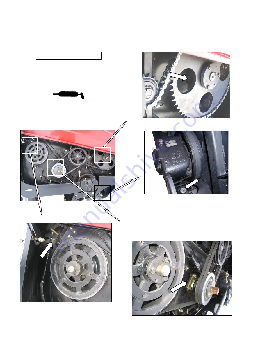
LUBRICATE THE HEADER (Cont’d) 


REEL SHAFT BEARING (1 PLC) 

A30-D HEADER RH SIDE 

SICKLE HEAD BEARING (1 PLC) 

High Temperature Extreme 

Pressure (EP2) Performance With 

1% Max Molybdenum Disulphide 

(NLGI Grade 2)  Lithium Base


SICKLE DRIVE BEARING (1 PLC) 

AUGER SHAFT BEARING (1 PLC) 

NOTE 

To prevent binding and/or excessive 

wear caused by sickle pressing on 

guards, do not over grease. If more 

than 6 to 8 pumps of the grease gun 

are required to fill the cavity, replace 

the seal in the sickle head.  

Summary of Contents for A30-D

Page 1: ...Form 169078 Revision C 1 A30 S A30 D and A40 D Auger Self Propelled Windrower Header Unloading and Assembly Instructions Published November 2010 ...

Page 2: ...delivery requirements for the MacDon Model A30 S A30 D and A40 D Auger Headers including a Grass Seed version Use the Table of Contents to guide you to specific areas CAREFULLY READ ALL THE MATERIAL PROVIDED BEFORE ATTEMPTING TO UNLOAD ASSEMBLE OR USE THE MACHINE MACDON A40 D SELF PROPELLED AUGER HEADER ...

Page 3: ...17 STEP 13 ATTACH HEADER TO WINDROWER 18 STEP 14 MODIFY HYDRAULICS 21 A A30 S AND A30 D 21 B A40 D 21 I M100 21 II M150 23 III M200 24 IV M205 26 STEP 15 CONFIGURE REVERSER VALVE JUMPER HOSE 27 STEP 16 ATTACH HYDRAULICS 29 A A30 S A30 D 29 I M100 M150 M200 M205 29 B A40 D 31 I M100 33 II M150 33 III M200 33 IV M205 33 STEP 17 CONFIGURE HOSE ROUTING 34 STEP 18 REPOSITION WOBBLE BOX BREATHER 34 STEP...

Page 4: ...extinguisher on the machine Be sure the extinguisher is properly maintained and be familiar with its proper use Keep young children away from machinery at all times Be aware that accidents often happen when the operator is tired or in a hurry to get finished Take the time to consider the safest way Never ignore warning signs of fatigue Wear close fitting clothing and cover long hair Never wear dan...

Page 5: ...orking with electrical equipment Be sure all electrical outlets and tools are properly grounded Use adequate light for the job at hand Keep machinery clean Do not allow oil or grease to accumulate on service platforms ladders or controls Clean machines before storage Never use gasoline naphtha or any volatile material for cleaning purposes These materials may be toxic and or flammable When storing...

Page 6: ...rque values by 5 B SAE BOLTS BOLT DIA A in NC BOLT TORQUE SAE 5 SAE 8 lbf ft N m lbf ft N m 1 4 9 12 11 15 5 16 18 24 25 34 3 8 32 43 41 56 7 16 50 68 70 95 1 2 75 102 105 142 9 16 110 149 149 202 5 8 150 203 200 271 3 4 265 359 365 495 7 8 420 569 600 813 1 640 867 890 1205 Torque categories for bolts and capscrews are identified by their head markings C METRIC BOLTS BOLT DIA A STD COARSE BOLT TO...

Page 7: ... RING TYPE a Inspect O ring and seat for dirt or obvious defects b On angle fittings back off the lock nut until washer A bottoms out at top of groove B in fitting c Hand tighten fitting until back up washer A or washer face if straight fitting bottoms on part face C and O ring is seated d Position angle fittings by unscrewing no more than one turn e Tighten straight fittings to torque shown f Tig...

Page 8: ...3048 meters per second m s miles per hour mph x 1 6063 kilometers per hour km h Volume US gallons US gal x 3 7854 liters L ounces oz x 29 5735 milliliters ml cubic inches in 3 x 16 3871 cubic centimeters cm3 or cc Weight pounds lb x 0 4536 kilograms kg DEFINITIONS TERM DEFINITION API American Petroleum Institute APT Articulating Power Tongue ASTM American Society Of Testing And Materials Header Th...

Page 9: ...tor WARNING Be sure forks are secure before moving away from load Stand clear when lifting IMPORTANT Do not unload using lean bar for lifting Chain hook slots in lean bar are only for laying the machine over into working position after it is on the ground NOTE Take care not to bend parts on back tube a Approach header from either its topside or underside and slide forks A in underneath lifting fra...

Page 10: ...ier prior to laying the header down a Unpack skid shoe bundle b Remove two clevis pins C from each skid shoe c Remove nuts bolts and clips D from skid shoe d Insert tabs on skid shoe into slots E on cutterbar at inboard mounting locations on frame and secure with clevis pin C e Attach clips D with bolts and nuts removed at step c to secure skid shoe to cutterbar NOTE Use a socket and ratchet wrenc...

Page 11: ...tabs on roller assembly into slots C on cutterbar at outboard mounting locations on frame and secure to support bracket with locking pin A at lowest position e Attach clips B with bolts and nuts removed at step c to secure roller assembly to cutterbar f Tighten nuts NOTE Use a socket and ratchet wrench to access the nuts g Remove locking pin A and adjust rollers to desired height Re install both l...

Page 12: ... minimum 4 feet 1 2 m vertical chain height CHAIN TYPE OVERHEAD LIFTING QUALITY 1 2 INCH MINIMUM WORKING LOAD 5000 lb 2270 kg CAUTION Stand clear when lowering as machine may swing NOTE Do not lift at lean bar when unloading from trailer This procedure is only for laying the machine over into working position d Raise forks until lift chains are fully tensioned e Back up SLOWLY while simultaneously...

Page 13: ...C Secure pin with lynch pin NOTE In soft conditions use a wooden block under the stand k Lower header onto stand D STEP 6 REMOVE SHIPPING STANDS a Remove two bolts E from shipping stand F b Remove hairpin from pin G c Hold shipping stand F remove pin G and remove stand Discard stand and hardware d Repeat above steps for opposite shipping stand e Remove four bolts H and remove angle J Discard angle...

Page 14: ... remove lean bar b Attach extensions C to lean bar with four bolts D and nuts provided c Re attach lean bar to header with existing hardware at desired location Tighten bolts d Attach LH divider assembly E to LH end of lean bar with two bolts F and nuts provided The divider may be positioned as shown or using the optional mounting hole G e Install U bolt H and tighten all bolts f Repeat for RH div...

Page 15: ...nd loosen bolt B b Slide pan extensions C and swath forming rods inboard to desired position and align holes c Re install two bolts A Tighten bolts A and B d Repeat for opposite pan extension STEP 10 ADJUST LIGHTS a Position amber light supports perpendicular to header b Check that pivot bolt is tight enough to hold light support in upright position yet still allow light to pivot out of the way of...

Page 16: ...ver A with bolts B jam nut D washer E and nut F from previous step e Tighten flange nut F enough to hold deflectors C in position but still allow deflectors to move f Tighten jam nut D against cover while holding bolt B g Remove lynch pin G from adjuster rod H and locate rod in hole in side deflector C Secure with lynch pin G h Repeat for other deflector i Invert forming shield to installation pos...

Page 17: ...per hole Hardware is supplied with forming shield kit c Remove the two clevis pins C from forward end of forming shield d Position forming shield under the windrower frame e Locate forming shield onto bolts A in windrower legs and secure with clevis pins C and lynch pin f Lift the aft end of the forming shield and attach straps D to pins E on windrower frame Install washer and hairpin to secure st...

Page 18: ...r shield G to middle position Loosen handles H if required STEP 13 ATTACH HEADER TO WINDROWER a Remove pins A from left and right header boots IMPORTANT To prevent damage to the lift system when lowering header lift linkages without a header or weight box attached to windrower ensure that float engagement pin is installed in storage location C and not installed at hole location D CAUTION Check to ...

Page 19: ...ns 4 Adjust link to required length for proper header angle by rotating barrel G Tighten nut F against barrel A slight tap with a hammer is sufficient 5 Proceed to step e HYDRAULIC LINK WITHOUT SELF ALIGNMENT KIT M200 STD M150 AND M100 OPTIONAL 1 Activate HEADER TILT cylinder switches on GSL to extend or retract center link cylinder so that the hook lines up with the header attachment pin 2 Stop e...

Page 20: ...ition handle is down e Raise the header fully with the HEADER UP switch on the GSL Stop engine and remove key DANGER To avoid bodily injury from fall of raised header always engage header lift cylinder stops when working on or around raised header f Pull lever A and rotate toward header to release and lower cylinder stop B onto cylinder Repeat for both lift cylinders g Install pin C through each b...

Page 21: ...key STEP 14 MODIFY HYDRAULICS A A30 S AND A30 D The M100 M150 and M200 are factory equipped with A30 S and A30 D header hydraulics and electrical harness Proceed to STEP 15 CONFIGURE REVERSER VALVE JUMPER HOSE The M205 hydraulics need to be modified to accept an A Series header and kits B5491 B5492 and B5497 should have been supplied with your header Install the kits in accordance with the instruc...

Page 22: ...e coupler O onto fitting at port R1 on valve block D IMPORTANT Make sure O ring is on JIC threads in port R1 to ensure a proper seal with the coupler O If O ring is missing re use O ring from fitting N 8 Remove and discard the cap P and adapter fitting Q from the small coupler assembly R 9 Install the small coupler subassembly R onto the tee S on valve block D NOTE Adjacent hoses may require sligh...

Page 23: ...assemblies C and D from hoses in bundle E from header and remove caps 3 Install smaller coupler assembly C in R2 port in valve block A and the larger coupler assembly D in R2 port in valve block B b Proceed to Step 15 CONFIGURE REVERSER VALVE JUMPER HOSE M150 WITHOUT REVERSER VALVE R2 M150 WITH REVERSER VALVE A R2 R2 B M150 WITHOUT REVERSER VALVE A R2 B R2 M150 WITH REVERSER VALVE C D A B M150 WIT...

Page 24: ...ssemblies C and D from hoses in bundle E from header and remove caps c Install smaller coupler assembly C in R2 port in valve block A and the larger coupler assembly D in R2 port in valve block B NOTE Adjacent hoses may require slight repositioning to allow access for new hoses d Proceed to Step 15 CONFIGURE REVERSER VALVE JUMPER HOSE M200 WITH REVERSER C D E C D M200 WITH REVERSER R2 R2 A B ...

Page 25: ...e cap F and adapter fitting G with O ring from the large coupler H d Install larger coupler H onto fitting at port R2 on valve block B e Remove cap from smaller coupler assembly C and install assembly in port R2 on valve A IMPORTANT Make sure O ring is on JIC threads in port R1 to ensure a proper seal with the coupler H If O ring is missing re use O ring from fitting G f Proceed to Step 16 ATTACH ...

Page 26: ...to accept an A Series auger header and kits B5491 B5492 and B5497 should have been supplied with your header b Install the kits in accordance with the instructions that were supplied with the kits to achieve the configuration shown above c Proceed to STEP 16 ATTACH HYDRAULICS AUGER HEADER HYDRAULICS ...

Page 27: ...Check the routing of the jumper hose as follows and change as required b Move LH windrower platform to open position to expose hydraulic valve blocks c To route hose B from A40 D position to A30 S A30 D position 1 Disconnect jumper hose B from port C2 fitting on header drive valve block C 2 Rotate 90 fitting D under reverser valve block A so that it points aft 3 Remove cap from 90 fitting in port ...

Page 28: ...fitting D under reverser valve block A so that hose can be routed to port C2 on header drive valve block C 3 Remove cap from fitting in header drive valve block port C2 and connect jumper hose B to port C2 fitting 4 Install cap removed in step 3 on 90 fitting in port R4 on reverser valve block A e Move LH maintenance platform to normal operating position B R4 A D C2 B D A C ...

Page 29: ... bundle E d Move hose bundle E to header e Rotate lever D clockwise and engage in bracket to store IMPORTANT If the hose bundle contains four hoses draper header operation only three are required to power the A30 header Ensure loose hose is properly secured to avoid contact with the drivelines f Route hoses E from windrower through support F and access hole G in header frame g Remove cover on head...

Page 30: ...ectors onto mating receptacles as shown until collars on receptacles snap into lock position k Activate header tilt cylinder switches to extend and retract center link Check for sufficient clearance between hoses and electrical harness RETURN CASE DRAIN HEADER DRIVE ...

Page 31: ... to fully up position to release the hose bundle E d Move hose bundle E to header e Rotate lever D clockwise and engage in bracket to store f Route hoses E from windrower through support F and access hole G in header frame alongside hose bundle H Hose bundle H will be attached later in the procedure g Remove cover on header electrical receptacle J h Push connector onto receptacle and turn collar o...

Page 32: ... with inch carriage bolt M and locking nut Install bolt from under bracket 4 Repeat above steps at the two other brackets on hose support m Route reel auger return and auger pressure hose bundle H from header to windrower and locate bundle above existing hose support N as shown n Secure with three straps K and lower lever D continued next page H N K D GRASS SEED HEADER AUGER and REEL PRESSURE KNIF...

Page 33: ...n below I M100 II M150 III M200 IV M205 M150 WITHOUT REVERSER VALVE AUGER PRESSURE REEL AUGER RETURN M150 WITH REVERSER VALVE REEL AUGER RETURN AUGER PRESSURE M200 WITHOUT REVERSER VALVE REEL AUGER RETURN AUGER PRESSURE AUGER PRESSURE REEL AUGER RETURN M200 WITH REVERSER VALVE AUGER PRESSURE REEL AUGER RETURN AUGER REEL PRESSURE REEL AUGER RETURN REEL AUGER RETURN AUGER REEL PRESSURE ...

Page 34: ...se C at tee 2 Disconnect hose D at reel motor 3 Disconnect tee E at motor lower port d Re connect hoses as follows 1 Relocate tee E to upper port 2 Connect hose D to tee 3 Connect hose C to motor lower port e Close drive shield before engaging header STEP 18 REPOSITION WOBBLE BOX BREATHER a Move breather dipstick B to back port and install plug A in forward port at wobble box es b Check oil level ...

Page 35: ...ave excess grease on fitting to keep out dirt d Replace any loose or broken fittings immediately e If fitting will not take grease remove and clean thoroughly Also clean lubricant passageway Replace fitting if necessary f Refer to the illustrations on following pages for lubrication points High Temperature Extreme Pressure EP2 Performance With 1 Max Molybdenum Disulphide NLGI Grade 2 Lithium Base ...

Page 36: ...excessive wear caused by sickle pressing on guards do not over grease If more than 6 to 8 pumps of the grease gun are required to fill the cavity replace the seal in the sickle head REEL SHAFT BEARING 1 PLC High Temperature Extreme Pressure EP2 Performance With 1 Max Molybdenum Disulphide NLGI Grade 2 Lithium Base A30 S HEADER LH SIDE SICKLE HEAD BEARING 1 PLC ...

Page 37: ...excessive wear caused by sickle pressing on guards do not over grease If more than 6 to 8 pumps of the grease gun are required to fill the cavity replace the seal in the sickle head AUGER SHAFT BEARING 1 PLC REEL SHAFT BEARING 1 PLC A30 D HEADER LH SIDE High Temperature Extreme Pressure EP2 Performance With 1 Max Molybdenum Disulphide NLGI Grade 2 Lithium Base ...

Page 38: ...ture Extreme Pressure EP2 Performance With 1 Max Molybdenum Disulphide NLGI Grade 2 Lithium Base SICKLE DRIVE BEARING 1 PLC AUGER SHAFT BEARING 1 PLC NOTE To prevent binding and or excessive wear caused by sickle pressing on guards do not over grease If more than 6 to 8 pumps of the grease gun are required to fill the cavity replace the seal in the sickle head ...

Page 39: ...more than 6 to 8 pumps of the grease gun are required to fill the cavity replace the seal in the sickle head SICKLE HEAD BEARING 1 PLC SICKLE DRIVE BEARING 1 PLC GAUGE ROLLER BEARINGS 2 PLCS BOTH SIDES IF INSTALLED High Temperature Extreme Pressure EP2 Performance With 1 Max Molybdenum Disulphide NLGI Grade 2 Lithium Base A40 D HEADER LH SIDE TINE BAR BEARING 4 PLCS EACH TINE BAR ...

Page 40: ...HEADER RH SIDE NOTE To prevent binding and or excessive wear caused by sickle pressing on guards do not over grease If more than 6 to 8 pumps of the grease gun are required to fill the cavity replace the seal in the sickle head SICKLE HEAD BEARING 1 PLC High Temperature Extreme Pressure EP2 Performance With 1 Max Molybdenum Disulphide NLGI Grade 2 Lithium Base ...

Page 41: ...LUBRICATE THE HEADER Cont d HAY CONDITIONER HAY CONDITIONER ROLL SHAFT BEARINGS 2 PLCS ROLL SHAFT BEARINGS 2 PLCS ROLL PIVOT 1 PLC BOTH SIDES High Temperature Extreme Pressure EP2 Performance With 1 Max Molybdenum Disulphide NLGI Grade 2 Lithium Base ...

Page 42: ...RSALS 2 PLCS DRIVELINE UNIVERSALS 2 PLCS DRIVELINE SHAFTS 1 PLC DRIVELINE UNIVERSALS 2 PLCS DRIVELINE SHAFTS 2 PLCS A30 D and A40 D 10 MOLY GREASE IS RECOMMENDED FOR DRIVELINE SHAFT SLIP JOINTS ONLY 10 MOLY GREASE IS RECOMMENDED FOR DRIVELINE SHAFT SLIP JOINTS ONLY High Temperature Extreme Pressure EP2 Performance With 1 Max Molybdenum Disulphide NLGI Grade 2 Lithium Base ...

Page 43: ... d OILING Apply oil to upper edge of lower spans when oiling chains SAE 30 REEL DRIVE CHAIN 1 PLC OIL KNIFE DAILY EXCEPT IN SANDY SOIL AUGER DRIVE CHAIN 1 PLC WOBBLE BOX A30 S 1 PLC A30 D A40 D 2 PLCS CHECK OIL LEVEL WITH TOP OF WOBBLE BOX HORIZONTAL CHECK ROLL GEARBOX 1 PLC ...

Page 44: ...riate section for your particular header I A30 S SINGLE KNIFE a Open shield on header RH side b Reel drive belts A should deflect 3 16 in 4 mm when a load of 8 12 lbf 35 40 N is applied to each belt at mid span c Reel drive chain B slack should be 1 4 in 6 mm d Close shield e Open shield on header LH side f Sickle drive belt C should deflect 1 4 inch 6 mm when a load of 20 lbf 80 N is applied at m...

Page 45: ...an j Close shield k Proceed to Section 20B AUGER STRIPPER BAR CLEARANCE III A40 D DOUBLE KNIFE a Open shield on header RH side b Sickle drive timing belt M should deflect 0 55 inch 14 mm when a load of 5 6 5 lbf 22 30 N is applied at mid span c Open shield on header LH side d Sickle drive timing belt N should deflect 0 55 inch 14 mm when a load of 5 6 5 lbf 22 0 N is applied at mid span e Sickle d...

Page 46: ...delines only Tines may slightly contact the guards but not the knife sections or the auger pan a Rotate reel slowly by hand and check tine clearance at knife and pan Flex tines to simulate crop loaded position to ensure tine clearances to knife sections and auger pan are adequate for working conditions b Check that the reel rotates freely NOTE In order to set the reel as close as possible to the k...

Page 47: ...ean bar and lifting The force to lift should be 75 85 lbf 335 380 N and should be approximately the same at both ends b Perform the following steps to adjust the float if necessary 1 Raise the header fully shutdown the engine and remove the key 2 Turn drawbolt A clockwise to increase float makes header lighter or counter clockwise to decrease float makes header heavier 3 Re check the float A ...

Page 48: ...hine e Place float pins A in locked out position CAUTION Check to be sure all bystanders have cleared the area f Start engine and set header approximately six inches 150 mm off ground Check that member B is against link C g Note high and low end of header h Place wooden blocks under header cutterbar and legs i Lower header onto blocks so that members B lift off links C j Shutdown the engine and re...

Page 49: ...itioner roll to achieve consistent intermesh across the rolls d Loosen bolt D and rotate cover E to expose access port F e Check roll timing by examining distance X at each end of the rolls F Each steel bar on one roll should be centered between two bars of the other roll so that distance X is 0 5 inches 12 mm f If required adjust the roll timing as follows 1 Loosen four bolts G in slots of yoke p...

Page 50: ...t skid shoes or for any reason a Raise header and engage lift cylinder lockouts b Check that pins are installed in the same position in all skid shoes gauge rollers H LIGHTS The hazard lights which are mounted on both ends of the header are activated by switches in the M Series windrower cab Check for operation during run up a Check that pivot bolt is tight enough to hold light support in upright ...

Page 51: ...ies Self Propelled Windrower Operator s Manual a Operate the machine slowly for 5 minutes watching and listening FROM THE WINDROWER SEAT for binding or interfering parts b Run the machine for 15 minutes at maximum engine operating rpm and perform the run up check as listed on the Pre Delivery Checklist yellow sheet attached to this instruction to ensure the machine is field ready c Check actual sp...

Page 52: ...nd tapping knife head with a hammer Re tighten bolt 2 Adjust guard alignment as follows The guard straightening tool MacDon 140135 is available from your MacDon Dealer i Position tool as shown at and pull up ii Position tool as shown and push down K MANUALS a Place Operator s Manual Form 169000 and Parts Catalog Form 169002 in storage case in the windrower cab b This instructional manual should be...

Page 53: ...NOTES Form 169078 Revision C 53 ...

Page 54: ... range 19 Check that header is level 48 Check header flotation 75 85 lbf 335 380 N m 47 Check lean bar is adjusted at a setting appropriate for first crop 15 Check skid shoes are evenly adjusted at a setting appropriate for first crop 50 Check wobble box lube level and breather position 34 Check rear and side forming shields evenly set to desired position 16 Grease all bearings and drivelines 35 4...

Page 55: ......

Page 56: ...Missouri United States 64153 1924 t 816 891 7313 f 816 891 7323 MacDon Australia Pty Ltd A C N 079 393 721 P O Box 243 Suite 3 143 Main Street Greensborough Victoria Australia 3088 t 03 9432 9982 f 03 9432 9972 CUSTOMERS www macdon com DEALERS www macdondealers com Trademarks of products are the marks of their respective manufacturers and or distributors Printed in Canada ...

Reviews: