10.
Some material contains chemicals which may be toxic. Take caution to prevent working
dust inhalation and skin contact. Follow material supplier safety data.
11.
The damaged tools, accessories and waste packaging should be sorted for
environmentally friendly recycling and in accordance with local laws.
12.
Always lead the power supply cord away from the tool towards the rear.
13. Always be sure to have a firm footing. Wear safety belt when using this tool in high
locations and ensue no one is below.
SAVE THESE INSTRUCTIONS.
WARNING! MISUSE or failure to follow the safety rules stated in this instruction manual
may cause serious personal injury.
INSTRUCTIONS FOR OPERATION
Switch Action
CAUTION:
Before plugging in the tool, always check to see
that the switch trigger actuates properly and
returns to the “OFF” position when released.
To start the tool, simply pull the switch trigger. Tool
speed is increased by increasing pressure on the
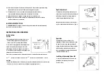
switch trigger. Release the trigger to stop. (Fig. 1)
For continuous operation, pull the switch trigger and
then push in the lock button. (Fig. 1)
This tool has a reversing switch to change the direction of rotation. Move the switch lever to
the
position for clockwise rotation or the
position for counterclockwise rotation.
CAUTION:
Always check the direction of rotation before operation. Changing the direction of rotation only
after the tool comes to a complete stop, otherwise it may damage the tool.
Depth Adjustment
The depth can be adjusted by turning the lock
ring. 1/6 turn of the lock ring equals 0.25mm (10
mil) change in depth. Stop turning when you
obtain the proper depth setting. (Fig. 2)
Always drive a trial screw into your material or
a piece of duplicate material before use. (Fig. 3)
Operation
The bit will not rotate even if the tool is
switched on. Fit the screw onto the point of the
bit, push in on the screw, and the clutch will
engage, then the bit will rotate. Keep your hand
with the bit in a straight line to ensure the
pressure applied by the hand can be delivered
to the bit effectively. (Fig. 4)
Installing or Removing Driver Bit
To remove the bit, first remove the locator by
pulling the lock ring away from the gear
housing. (Fig. 5)
Summary of Contents for SSCREW-001
Page 1: ......


