- 17 -
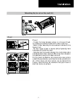
Phase 1
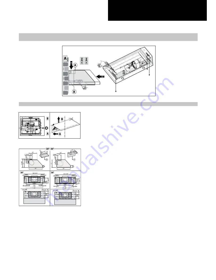
- Position the fixing template surface A on the wall (Fig.8),
(considering the minimum distance from the cooker top).
- Make 4 holes respecting the measurement indicated in the
figures (Fig.7).
- Fix the 2 upper screws A (fig.9A) without tightening them
completely along with the plugs.
- Hang the hood on the wall, aligning it in a horizontal position
and tighten/fasten the 2 screws A. When it has been adjusted,
fix it definitively using the 2 safety screws B.
For the various installations use screws and screw anchors
suited to the type of wall (e.g. reinforced concrete, plasterboard,
etc.). If the screws and screw anchors are provided with the
product, check that they are suitable for the type of wall on
which the hood is to be fixed.
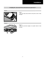
Installation
Phase 1
Mounting the hood on the wall 8.3
fig.9A
fig.8
fig.7
Summary of Contents for PVUS930
Page 2: ......
Page 9: ... 9 Technical data 2 2 29 15 16 35 15 16 11 1 3 8 10 1 13 16 3 12 3 1 4 ...
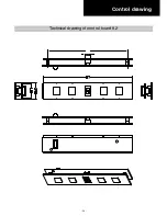
Page 20: ... 20 Control drawing Technical drawing of control board 9 2 ...
Page 28: ... 28 Electrical Assembly ...
Page 29: ... 29 Wiring Diagram ...
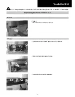
Page 32: ... 32 Phase 5 Remove all the screws indicated Motor Phase 5 ...
Page 35: ... 35 Exploded view Models PVUS930 PVUS936 ...
Page 38: ...29 5829 ...


