- 15 -
Installation
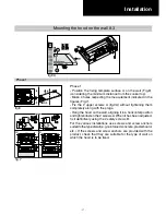
Phase 4
Phase 3
- Attention!
This product utilizes the air evacuation hole available in 2 diff erent
positions, which can be used according to your requirements;
1 – In the upper part of the hood Fig.1A.
2 – In the rear part of the hood Fig.1B.
- The air evacuation fl ange is supplied with the rectangular shape
X and circular shape Y (Fig.1).
Phase 4
- Version with air evacuation hole in the upper part of the
hood (Fig.3):
This product is supplied with the air outlet in the upper part
and the electric connection box positioned in the rear part of
the hood.
- If a rectangular air outlet pipe is used E, the hood is already
set-up (Fig.3.A).
- If, however, a circular air outlet pipe is to be used F, the 7
screws H must be removed along with the bracket X (Fig.3.B).
Phase 5
- Version with air evacuation hole in the rear part of the hood
(Fig.4):
If your requirements are the use of the air outlet in the rear
part of the hood (carry out all phases shown in figure 2),
remove the screws I (Fig. 4.A) that fix the motor bracket Y
and turn the entire motor unit and position it as indicated in
Fig.4.B. Put the motor bracket Y back in its seat and fix it with
the previously removed screws I.
Attention!
Whenever a circular air outlet pipe is to be used F, the
operation indicated in Fig.3.B must always be repeated.
Phase 3
fig.1
fig.3
Phase 5
fig.4
Summary of Contents for PVUS930
Page 2: ......
Page 9: ... 9 Technical data 2 2 29 15 16 35 15 16 11 1 3 8 10 1 13 16 3 12 3 1 4 ...
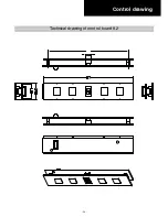
Page 20: ... 20 Control drawing Technical drawing of control board 9 2 ...
Page 28: ... 28 Electrical Assembly ...
Page 29: ... 29 Wiring Diagram ...
Page 32: ... 32 Phase 5 Remove all the screws indicated Motor Phase 5 ...
Page 35: ... 35 Exploded view Models PVUS930 PVUS936 ...
Page 38: ...29 5829 ...


