R30TS4
5-2-55, Minamitsumori, Nishinari-ku, Osaka 557-0063 JAPAN
Phone: +81(6)6659-8201 Fax: +81(6)6659-8510 E-mail: [email protected]
EM-9002 Rev.2 P. 4 / 5
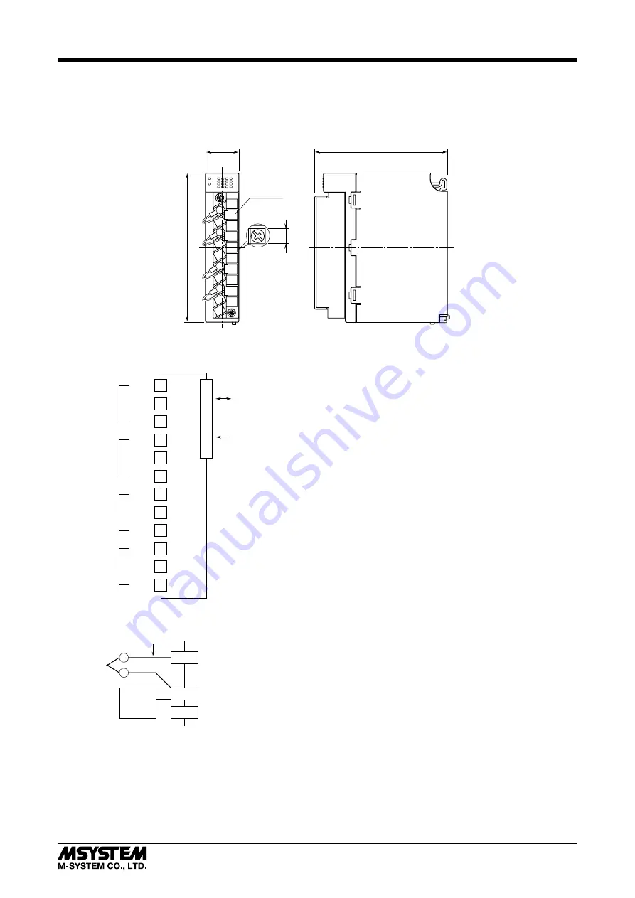
TERMINAL CONNECTIONS
Connect the unit as in the diagram below.
For thermocouple input, attach the CJC sensor together with input wining to the input screw terminals.
■
EXTERNAL DIMENSIONS unit: mm (inch)
110(4.33)
25(.98)
98(3.86)
20-M3
SCREW
6
(.24)
①
③
④
⑫
⑭ ⑤
⑥
⑦
⑧
⑨
⑩
⑮
⑲
⑳
RUN
ERR
⑰
②
11
13
16
18
■
CONNECTION DIAGRAM
1
2
11
+IN1
COM1
3
4
13
+IN2
COM2
+CJ1
+CJ2
6
7
16
+IN3
COM3
8
9
18
+IN4
COM4
+CJ3
+CJ4
■
INPUT CONNECTION EXAMPLE
+INn
+CJn
COMn
T/C
CJC
SENSOR
comp. leadwire
+
-
INPUT 1
INPUT 2
INPUT 3
INPUT 4
INTERNAL POWER
BUS CONNECTOR
INTERNAL BUS


