M3SMS
5-2-55, Minamitsumori, Nishinari-ku, Osaka 557-0063 JAPAN
Phone: +81(6)6659-8201 Fax: +81(6)6659-8510 E-mail: [email protected]
EM-7715 Rev.4 P. 3 / 4
TERMINAL CONNECTIONS
Connect the unit as in the diagram below or refer to the connection diagram on the side of the unit.
■
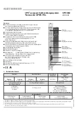
EXTERNAL DIMENSIONS unit: mm (inch)
7
8
5
6
1
2
3
4
106 (4.17)
12
(.47)
110.5 (4.35)
62 (2.44)
[5 (.20)]
• When mounting, no extra space is needed between units.
DIN RAIL
35mm wide
■
CONNECTION DIAGRAM
+
–
1
4
3
2
1
POTENTIOMETER
max.
min.
3
+
–
OUTPUT
5
6
U(+)
V(–)
POWER
7
8
■
WIRING INSTRUCTIONS
• Applicable wire size
Solid:
0.2 to 2.5 mm
2
(0.55 to 1.75 dia.)
Stranded: 0.2 to 2.5 mm
2
Tinning wire ends may cause contact failure
and therefore is not recommended.
Ferruled: 0.2 to 1.5 mm
2
(0.55 to 1.35 dia.)
The following Phoenix Contact terminals are
recommended:
AI 0,25-8YE
0.2 to 0.25 mm
2
AI 0,34-8TQ
0.25 to 0.34 mm
2
AI 0,5-8WH
0.34 to 0.5 mm
2
AI 0,75-8GY
0.5 to 0.75 mm
2
AI 1,0-8RD
0.75 to 1.0 mm
2
AI 1,5-8BK
1.0 to 1.5 mm
2
• Expose wire conductors by 8 mm (0.31”).
8 mm
8 mm
4 mm dia.
max.
4 mm dia.
max.
Wire exposure
Recommended
ferruled wire
CHECKING
1) Terminal wiring: Check that all cables are correctly con-
nected according to the connection diagram.
2) Power input voltage: Check voltage across the terminal
7 – 8 with a multimeter.
3) Input: Check voltage across the terminal 4(+) – 3(–) with
a voltmeter to show 0V at 0% potentiometer input and
the same voltage as that across 1(+) – 3(–) at 100% input.
4) Output: Check that the load resistance meets the de-
scribed specifications.
ADJUSTMENT PROCEDURE
This unit is calibrated at the factory with the total resist-
ance input, therefore you do not need any calibration if you
use the potentiometer’s total resistance.
When you don’t use the total resistance or in case of regular
calibration, adjust the output as explained in the following.
■
HOW TO CALIBRATE THE OUTPUT SIGNAL
Use a signal source and measuring instruments of sufficient
accuracy level. Turn the power supply on and warm up for
more than 10 minutes.
1) ZERO: Apply 0% input and adjust output to 0%.
2) SPAN: Apply 100% input and adjust output to 100%.
3) Check ZERO adjustment again with 0% input.
4) When ZERO value is changed, repeat the above proce-
dure 1) – 3).