background image

EXPLANATIONS OF TERMS & FUNCTIONS


COUNT OVERFLOW

Three overflow modes are selectable with the Programming 
Unit: Reset, Hold at 100% or Hold at 115%.
In Reset mode, the JPQ2 resets pulse count to zero as soon 
as the input reaches the span count value.  The span count 
is equal to the zero count, thus the JPQ2 never outputs 
100% in this sense.
In Hold at 100% mode, the JPQ2 stops counting at 100% 
input.  The count is held at the span count value, and the 
DC output is held at 100%.
In Hold at 115% mode, the JPQ2 continues counting until 
115% before holding the count and DC output.
In both modes, the Reset command input resets the count 
to zero and the JPQ2 returns to the output equivalent to 
zero count.
Input frequency does not affect the pulse counting of this 
unit, however, the minimum of 5-microsecond pulse width 
(50 msec. for mechanical contact input) is required to ac-
curately count the input pulses.
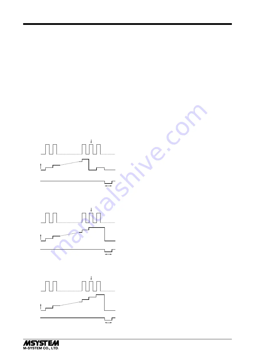
• Reset Mode

Input

Output

+

Reset

Short

Span Count

Min. 500 ms

Open

• Hold at 100% Mode

Input

Output

+

Reset

Short

Span Count

Min. 500 ms

Open

• Hold at 115% Mode

Input

Output

+

Reset

Short

Span Count

Min. 500 ms

Open


ALARM OUTPUT

Either Hi or Lo alarm output is supplied by a relay contact.  
The alarm setpoint and the deadband (hysteresis) are ad-
justable with the Programming Unit in percentage of the 
input range.  The alarm setpoint is selectable from -15 to 
+115%, while the deadband is from 0 to 20%. 
Once the relay contact trips, it is reset to the normal posi-
tion when the counter is reset by the external reset com-
mand.


RESET INPUT

When a reset input is turned on, the accumulated count 
in the internal counter goes back to zero.  The JPQ2 com-
pares the input to this internal count for the alarm function, 
therefore is affected by reset operations.
The reset input negative is connected to the input common.  
Short across the terminals 6 and 11 for the minimum of 
500 msec.


ZERO COUNT, SPAN COUNT

The count value equivalent to 0% output is called ‘Zero 
Count,’ while that equivalent to 100% is called ‘Span Count.’
The zero count is usually set to 0, and selectable up to one 
count below the span count.  The span count is selectable 
from one count above the zero count up to 99999999.
When a reset input is turned on, the output goes to 0% ac-
cording to the reset count.
With the ‘Hold at 115%’ overflow mode, the maximum count 
range is from 0 to 99999999, and the maximum effective 
count is 114999998.


DETECTING PULSE EDGE

• Open Collector & Mechanical Contact:

OFF (input monitor LED ON) to ON (input monitor LED 
OFF) or ON to OFF

• Voltage Pulse

A pulse rise detected when the input voltage goes above 
the detecting level (input monitor LED ON); a pulse sink 
detected when it goes below the level (input monitor LED 
OFF).

• Two-wire Current Pulse

The input resistor (100Ω) converts the current signal (0 – 
25mA) into 0 – 2.5V.  A pulse rise detected when the volt-
age goes above the detecting level (input monitor LED ON); 
a pulse sink detected when it goes below the level (input 
monitor LED OFF).

JPQ2

5-2-55, Minamitsumori, Nishinari-ku, Osaka 557-0063 JAPAN
Phone: +81(6)6659-8201  Fax: +81(6)6659-8510  E-mail: [email protected]

EM-1579  Rev.3  P. 3 / 8

Summary of Contents for JPQ2

Page 1: ...sent in the air install the unit inside proper housing with sufficient ventilation Do not install the unit where it is subjected to continuous vibration Do not subject the unit to physical impact Environmental temperature must be within 5 to 60 C 23 to 140 F with relative humidity within 30 to 90 RH in order to ensure adequate life span and operation WIRING Do not install cables close to noise sou...

Page 2: ...tra space is needed between units 3 9 4 CONNECTION DIAGRAM OUTPUT 1 2 U V POWER 7 8 PU 2x MODULAR JACK 9 10 ALARM OUTPUT 5 4 6 5kΩ Dry Contact or Mechanical Contact Input Connection Examples Vsns PWR 2 Wire Current Pulse Built in Excitation 5 4 6 Vsns 2 WIRE PICK UP External DC Supply 5 4 6 Vsns 2 WIRE PICK UP DC SUPPLY 100Ω Voltage Pulse 5 4 6 Vsns PWR 100Ω INPUT 5 4 6 SENSOR EXCITATION 11 RESET ...

Page 3: ...on when the counter is reset by the external reset com mand RESET INPUT When a reset input is turned on the accumulated count in the internal counter goes back to zero The JPQ2 com pares the input to this internal count for the alarm function therefore is affected by reset operations The reset input negative is connected to the input common Short across the terminals 6 and 11 for the minimum of 50...

Page 4: ... filter is usable for the input frequency 10 Hz or lower range and Low filter is usable for 500 Hz or lower For a mechanical contact input High setting is recom mended in order to eliminate unwanted counts caused by chattering EXAMPLE 1 VOLTAGE PULSE with Amplitude 5V p p DC Offset 2 5V Count Range 0 1000 Input type Voltage Pulse Input count Zero count set to 0 Span count set to 1000 ON 1 2 3 4 5 ...

Page 5: ...lector Mechanical contact Two wire current pulse 1 A specific sensitivity scale is applied according to the pulse amplitude setting The scaled input voltage is then com pared to the preset detecting level With DC coupling the scaled H level voltage must be higher than the detecting level so that the pulse state is accurately detected Setting Examples Voltage Pulse DC Offset Pulse Amplitude 2 PULSE...

Page 6: ...t the voltmeter across the terminals 4 6 2 Connect the ammeter to terminal 4 3 Turn the potentiometer until the meter shows the de sired value Check that the current value indicated on the ammeter is within the allowable limit If the value is greater than the limit lower the voltage value or connect a separate power source Otherwise the transmitter may fail 25 5 12 24 60 120 CURRENT mA VOLTAGE V V...

Page 7: ...or segment data input 11 P 0 Count mode 0 UP_EDGE Count at pulse rise 1 DOWN_EDGE Count at pulse sink 2 UPDOWN_EDGE Count at both pulse rise and sink 12 P 0 Count overflow mode 0 115 _HOLD Hold at 115 1 100 _HOLD Hold at 100 2 100 _RESET Reset at 100 14 P Numeric LO XXXXXXXXX 0 Input zero count 0 input 0 to 99999999 15 P Numeric HI XXXXXXXXX 1000 Input span count 100 input 0 to 99999999 19 P Perce...

Page 8: ...X 90 91 P P X 16 XXX XX Y 16 XXX XX Modification Code S Modifiable at any time P Modifiable only when the MAINTENANCE SWITCH is in the PRG mode CHECKING 1 Terminal wiring Check that all cables are correctly con nected according to the connection diagram 2 Power input voltage Check voltage across the terminal 7 8 with a multimeter 3 Input Check that the input signal is within 0 100 of the full scal...

Reviews: