background image

R7I4DECT-1-PA8A

5-2-55, Minamitsumori, Nishinari-ku, Osaka 557-0063 JAPAN
Phone: +81(6)6659-8201  Fax: +81(6)6659-8510  E-mail: [email protected]

EM-7779-F  Rev.1  P. 11 / 11

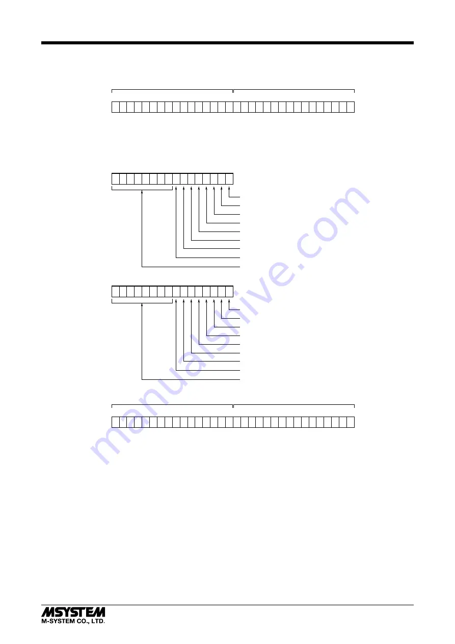
I/O DATA DESCRIPTIONS

 TOTALIZED PULSE INPUT MODULE (R7I4DECT-1-PA8A)

• 

Input Area Objects

0

15

16

31

32-bit binary data
When the channel is invalid, the pulse count is fixed to 0.

Accumulated pulse count (upper 16 bits)

Accumulated pulse count (lower 16 bits)

OUTPUT DATA n+0

• 

Output Area Objects

0

15

CH0 Pulse count reset bit
CH1 Pulse count reset bit
CH2 Pulse count reset bit
CH3 Pulse count reset bit

CH7 Pulse count reset bit

CH4 Pulse count reset bit
CH5 Pulse count reset bit
CH6 Pulse count reset bit

Unused

0

15

16

31

Preset value (upper 16 bits)

Preset value (lower 16 bits)

OUTPUT DATA n+1

0

15

OUTPUT DATA n+2

CH0 Pulse count preset bit
CH1 Pulse count preset bit
CH2 Pulse count preset bit
CH3 Pulse count preset bit

CH7 Pulse count preset bit

CH4 Pulse count preset bit
CH5 Pulse count preset bit
CH6 Pulse count preset bit

Unused


PULSE COUNT RESET

In n+0 word of the output data from host PC/PLC, the bits to reset the totalized values of the respective channels are allocated.
By changing the bits from 0 to 1, the totalized values of the respective channels are reset. 
Confirm that the totalized values are reset, and return the bits to 0.
Note that the next reset will not work if the reset bits remain at 1.


PULSE COUNT PRESET

Write the desired preset values in n+2 word and n+3 word of the output data from host PC/PLC. 
The bits to preset the totalized values of the respective channels are allocated in n+1 word.
By changing the bits from 0 to 1, the preset values are reflected to the totalized values of the respective channels.
Confirm that the totalized values are preset, and return the bits to 0.
Note that the next preset will not work if the preset bits remain at 1.

Summary of Contents for EtherCAT R7I4DECT-1-PA8A

Page 1: ...o the whole system and employ additional protective measures to ensure the CE conform ity POWER INPUT RATING OPERATIONAL RANGE Locate the power input rating marked on the product and confirm its opera...

Page 2: ...rmal RUN Device state Green Off INIT Blinking PRE OPERATIONAL Single Flash SAFE OPERATIONAL On OPERATIONAL ERR Error Red Off No error Blinking Invalid Configuration Single Flash Local error Double Fla...

Page 3: ...relevant to the pin number of the unit Perform wiring according to this instruction manual PULSE INPUT TERMINAL ASSIGNMENTS e CON connector Recommended cable connector 37104 000FL 3M Company does not...

Page 4: ...ling edge DI ON Edge direction for resetting pulse count by reset terminal Falling edge DI ON Rising edge DI OFF Falling edge DI ON Enabling or disabling pulse count reset by reset terminal Enable or...

Page 5: ...TION DIAGRAM Note In order to improve EMC performance bond the FE terminal to ground Caution FE terminal is NOT a protective conductor terminal SNSR EXC SNSR EXC FE PWR PWR 1 2 4 5 3 POWER SUPPLY IN S...

Page 6: ...an 0 the designated address is written in the resistor 0x0012 of ESC EtherCAT Slave Controller when R7I4DECT starts up Data Configuration Data are configured in accordance with the EtherCAT Modular De...

Page 7: ...BOOT state not supported 0x0016 Invalid MailBox configuration PREOP 0x0017 Invalid SyncManager configuration 0x001B SyncManager Watchdog Timeout 0x001D Invalid Output Configuration 0x001E Invalid Inp...

Page 8: ...vely In the data of RxPDO and TxPDO index sub index and the number of bit of each object which is referred to are stored For input data each object with the address starting with 0x6000 is referred to...

Page 9: ...it is allocated to object 0x1000 The device type is 5001 Table 8 Object Configuration For Device Type INDEX DATA TYPE BIT ACCESS VALUE CONTENT 0x1000 UINT32 32 RO 5001 Device type Error Register 0x100...

Page 10: ...onsists of 8 digits starting with two alpha numeral characters followed by six numeral characters The serial number is expressed as 32 bit data divided into 6 bit 6 bit and 20 bit groups with the firs...

Page 11: ...eset bit CH2 Pulse count preset bit CH3 Pulse count preset bit CH7 Pulse count preset bit CH4 Pulse count preset bit CH5 Pulse count preset bit CH6 Pulse count preset bit Unused PULSE COUNT RESET In n...

Reviews: