9.
“To Ins 3, 4” Switch: This switch, when pressed and locked to the in position,
will send the stereo signal that is present at the Aux In 2 jack to the Delta
H/W In 3 & 4. The Aux In 2 signal is then simultaneously muted to the
Omni stereo buss.
10 Effects (FX) Return: These 1/4” jacks accept TS plugs for unbalanced
operation, or TRS for balanced, and can be used to return the outputs of an
effects device to the Omni mixer. One plug can be plugged into the left input
for mono operation. When only the left jack used in this mono mode, the
signal is directed to the center of the stereo soundfield. When two plugs are
used, one in the left input and the other in the right, each is panned hard left
and hard right respectively.
11. Line 3 In & Line 4 In: These 1/4” jacks accept TS plugs for unbalanced
operation, or TRS for balanced, and are the Omni line inputs to Delta H/W
Ins 3&4.
12. 15 pin D-sub Connector: Utilizing the specially made shielded cable that
came with the Delta card, the Omni is connected to the Delta card via this 15
pin connector. This cable connects the Omni mic, instrument, and line ins to
the Delta H/W Ins 1-4, and the Delta H/W Outs 1-4 to the Omni mixer.
13. Insert 1 & Insert 2: These 1/4” TRS insert jacks access the Mic/Instr signal
path for unbalanced signal processing. An “insert cable” should be used,
which is a TRS plug to L&R mono TS plugs, where left is the send to the
effect and right is the return. Insert 1 is in the signal path of Mic/Instr Input
1, while Insert 2 is in the signal path of Mic/Instr Input 2.
4.3 Top Panel
The rear of the Omni top panel shows a mirror of the back panel, and is labeled
“Bottom Row” and “Top Row”. This is for your convenience when patching and
unpatching.
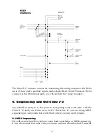
The Signal Flow chart on the front left of the Omni top panel gives you a quick
guide to how the signal moves in relation to the Omni. Should you need a quick
reminder, the flow chart is there for you. Signal flow is dealt with in more depth
in the section, “Omni Signal Flow Chart” later in this manual.
5. Operational Basics & Definitions
There are some basic concepts that apply to all audio gear. Understanding them
will help in your operation of the Omni I/O, as well as create a set of common
terms to use in our discussion of the Omni components.
5.1 Balanced Signals
A “balanced” line runs the signal on two wires of opposing polarity, as a ‘twisted
pair’ surrounded by a grounded shield. Doing so, it can send a ‘hotter’ signal
over a longer distance with less added noise. Using a TRS (tip-ring-sleeve, or
7


